One of the first steps towards the building of the modules was the procurement of the FREMO module end plates and the adoption of their standards . I joined FREMO in April 2011 when i had visited their Jahrestagung – Annual meet in Schutterwald near Offenburg, Germany. For the uninitiated , FREMO stands for “Freundeskreis Europäischer Modellbahner”, translated as Circle of Friends of European railway modellers…..
Initially i wanted to import the end plates from the regular supplier of FREMO in germany but then the Daga brothers suggested that we laser cut the modules ourselves through one of their vendors in Bengaluru. A quick internet search turned up the FREMO specifications for their finescale group – FREMO 87 or H0pur . While FREMO87 is different from the regular HO ( or H0-RE ) group but i still used the specifications anyway as i suspect they are no different . Here you can download a pdf of those specifications ………..
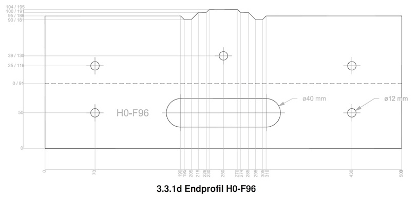 click on pic for a bigger image …..
Four hours later i had fed into corel draw the basic dimensions of four different type of modules and exported them into a DXF format. Off they went to the laser cutting firm and 2 weeks later we had the modules in our hand. The original FREMO end plates were of 12mm thickness and these end plates were 18mm thick. The wood was birch and overall the endplates looked great !!!! ….. Robust , strong , over engineered ……just the way i like it to be !!!
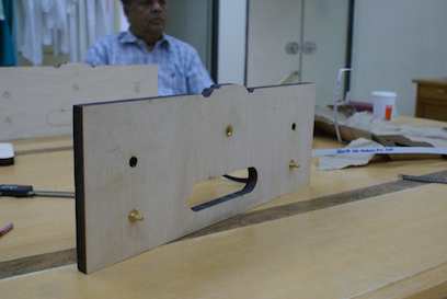
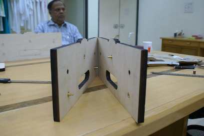
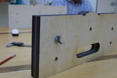
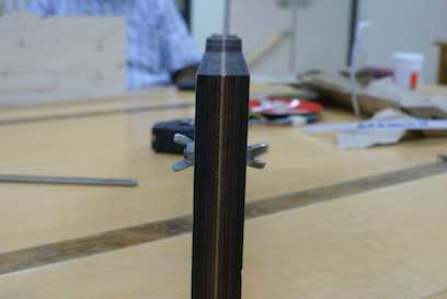
In the pics above, besides Rajendra Daga one can also see the alignment pins which very precisely aligns the modules and the wing nuts which secure them. Below is a closer view alongwith the adpated wrench which is needed to tighten the two…. as they say in german ….Zapfen und Hülse …….
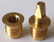
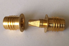
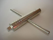
There was a great deal of debate whether or not these were to be used since they were expensive and would need to be imported from Germany . In the end , better sense prevailed ( i think !! ) and we sourced these from Roman Rachvoll from Bielefed Germany ….. his link here ……
In the pics above we see three of them per plate but two would suffice . We settled on the norm of male pin on the right side when facing the module from its side…….
Various methods of putting together the module parts were considered . The traditional glue and screw method was abandoned quickly – too primitive .Knocked down furniture type fixtures were considered as well but abandoned as the module pieces were not jointed in a rigid enough manner and there was a lot of rocking and play . Box joint , dovetail , tongue and groove joinery were discarded as well for i felt i did not have the skill set for such precision carpentery.
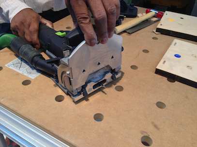
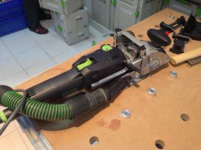
I finally settled for the Festool method of domino joinery ….. basically a mortise and tenon joinery method which was fast and easy to do……
here are pics of the festool domino jointer i used ….
and of the dominos itself …..i used the 5x19x30 mm size……
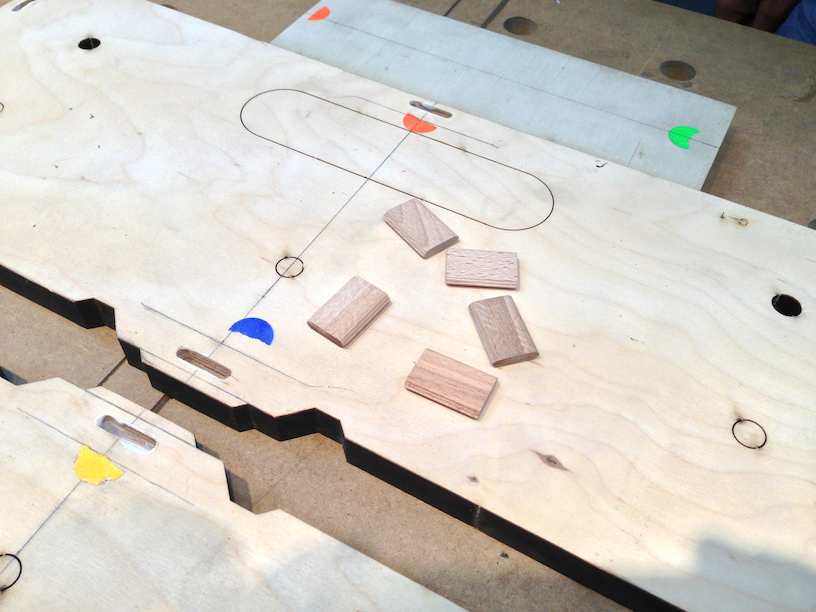
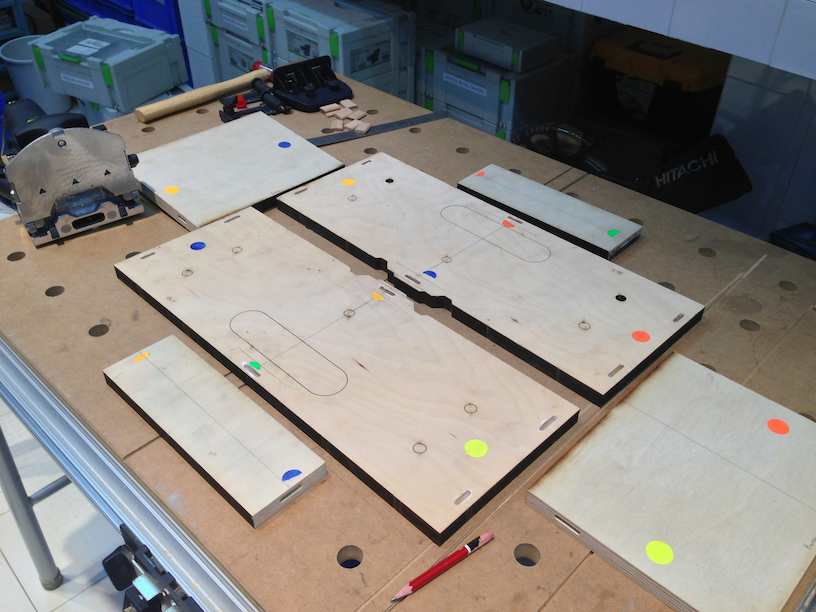
below we see the various parts cut out and the domino holes made . It is critical that one keeps track of which pieces mate together and to keep this relation true, i color coded the various pcs with stickers…..
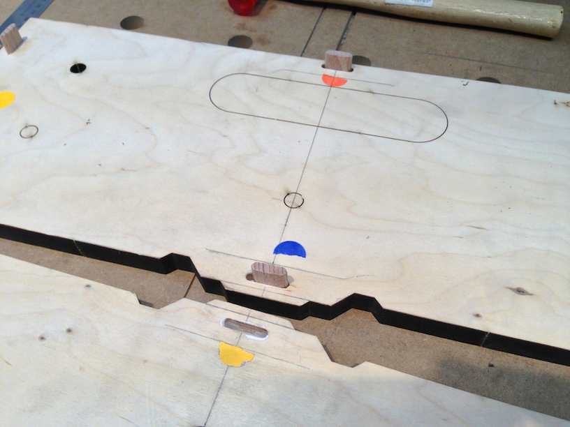
below are pics from the build of a smaller ” track master ” module to which the tracks of all future modules will be aligned too …. i forgot to take pictures of the assembly of the staging yard module …..but u will still get the picture anyway !!
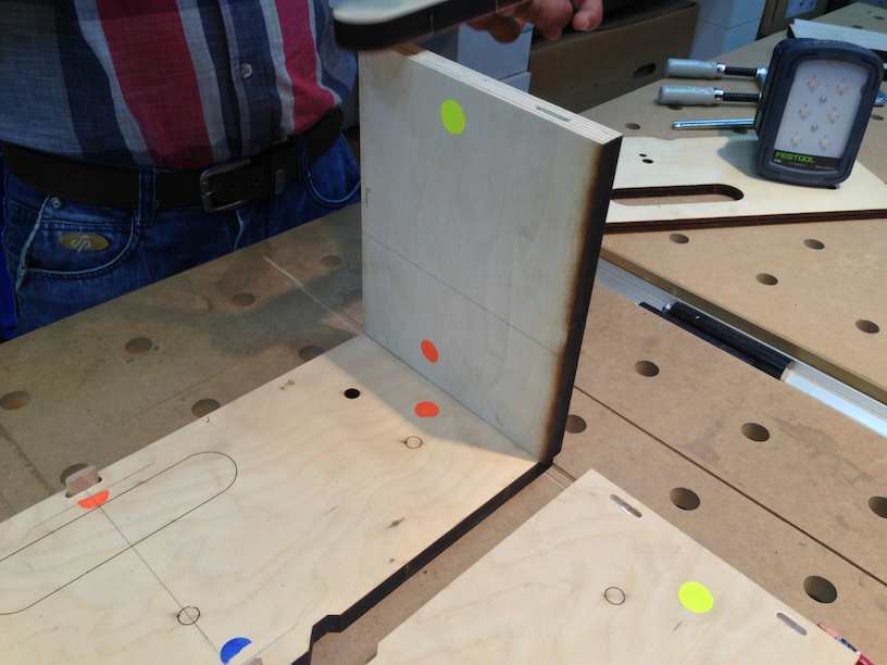
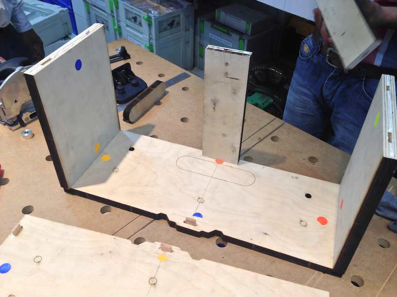
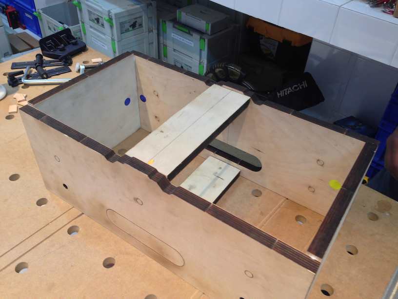
The box glued up assembled ……..
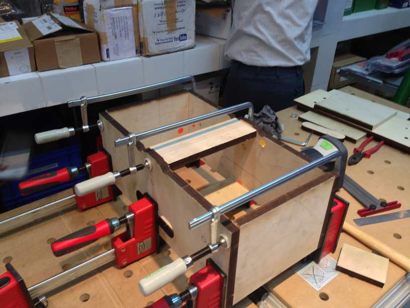
and then clamped ….
next player on the scene was the schneider sysmaster air compressor and grex pin nailer ….
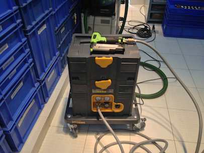
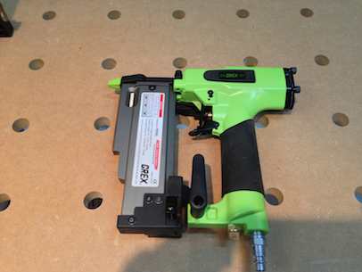
here is a video in german for the schneider sysmaster ….here is a video review for the grex pin nailer in english ……
the pin nails are themselves very small as u can see in the pic below and after putty filling . priming and painting disappear totally …..
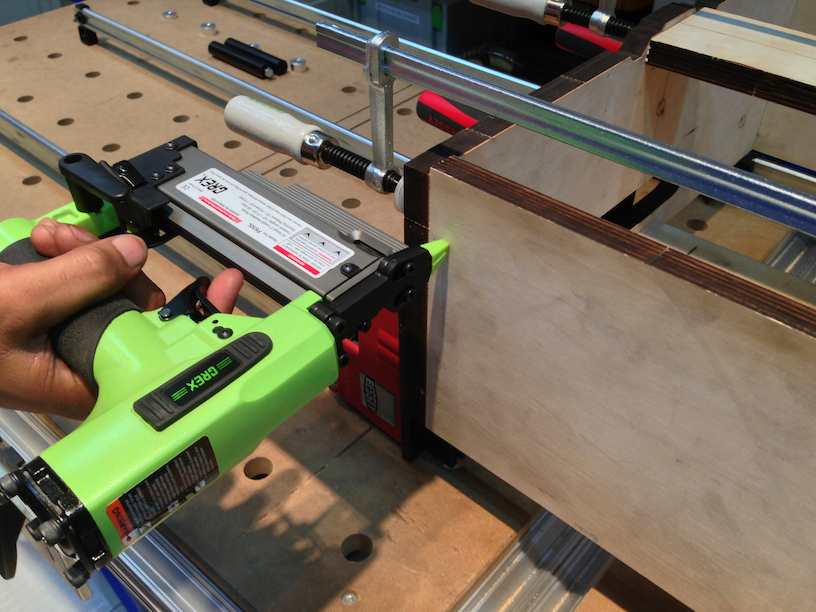
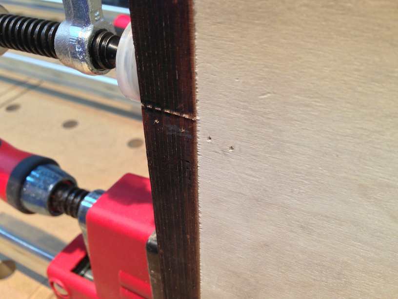
another advantage is that once the pin nails are in , one can unclamp the whole assembly and the glue joints will still be held together while the glue drys . This frees up the clamps to be used on another module , thus speeding up the entire assembly process considerably ….
While the Festool domino system is strong enough , adding the 23gg pin nails also adds considerably to the strength of the joint … below is a great video demonstrating the strengths of the domino jointing system with and without the pin nails and also the strength of various gluing options….
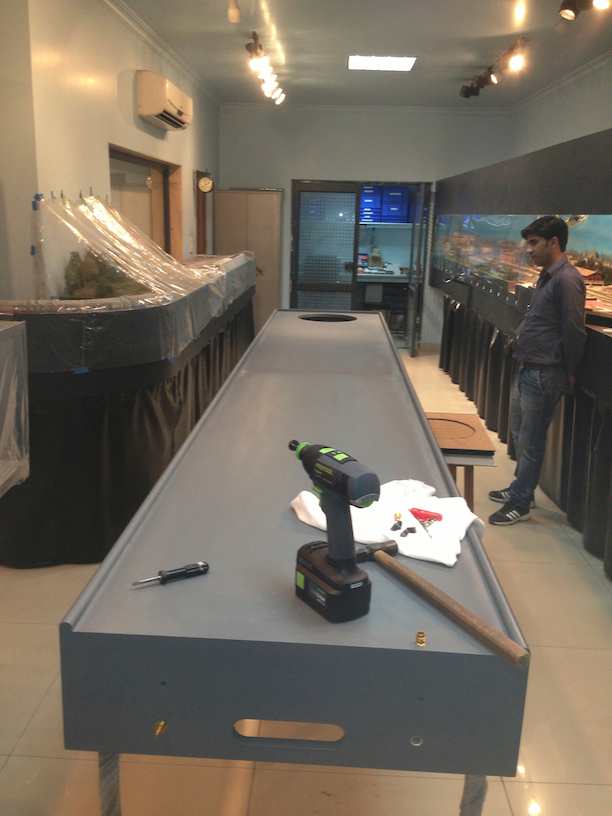
Below we see the two staging yard modules assembled , glued , clamped and nailed ……. they are nearly as long and tall as my assistant …..!!
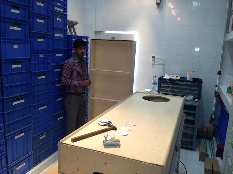
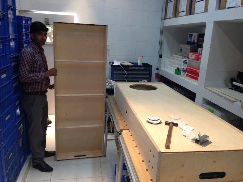
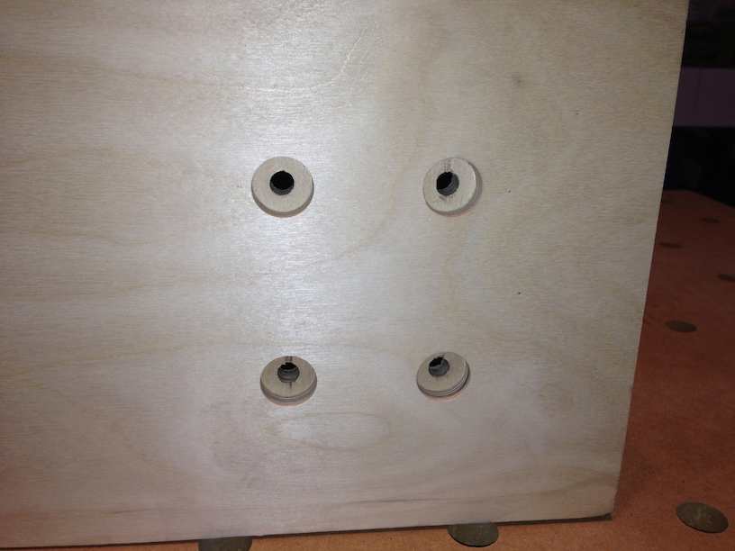
the drill holes for the legs were put in place using a forstner bit which would enable me to flush mount the nuts and bolts ….
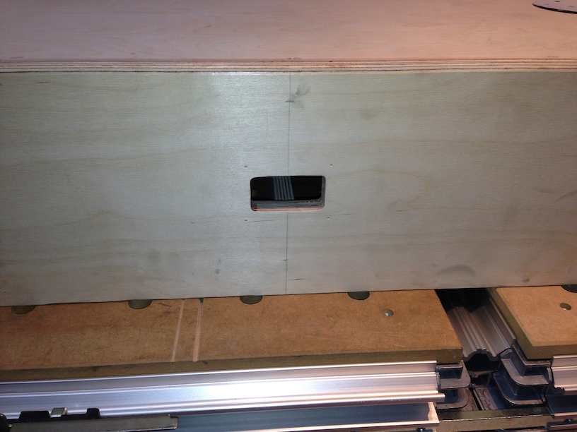
the cutouts for the digitrax UP panels routed out ….. a total of 4 of them , one on each of the 2 modules …
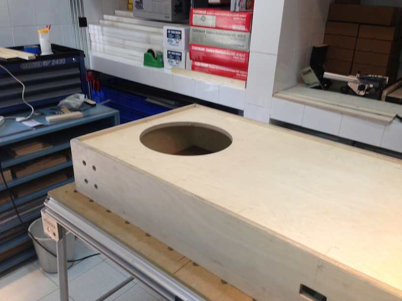
the hole for the turntable also routed out …….
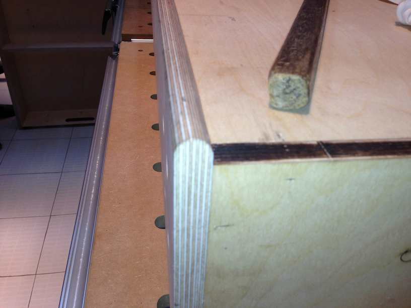
the edges of the fascia routed away using a 10mm round over bit …….
the modules were then thoroughly sanded down , then using putty we filled up the holes and other imperfections like scratches , nicks and joints . Two coats of primer went on , then another round of sanding and finally two coats of Polyurethane protective paint . Unfortunately , i did not take any pics of this entire process , so next time i do another module i will put them up…
I then installed the leg holding flanges onto the modules ……..
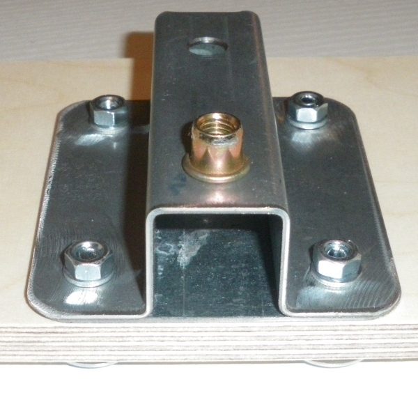
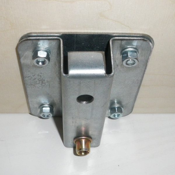
Again a lot of debate prevailed over whether or not these flanges should be imported in from Heiko Meyer in Germany – cost being the factor coupled with the belief that we could come up with a suitable alternative . I always believe model railroaders are always short of time and should not waste it in re-inventing the wheel. Obviously these leg holding plates were tried and tested by FREMO members earlier and therefore that was a good enough reason for me to go along with it as well. In retrospect , it has turned out to be a good decision as the plates were a cinch to install and the legs go in and out very quickly . The biggest plus of this system seems to be the very minute adjustments which one can make in getting the levels absolutely right .
I sourced 25mm square pipes and got them powder coated along with the plates giving a neater finish compared to how the flanges were initially delivered……
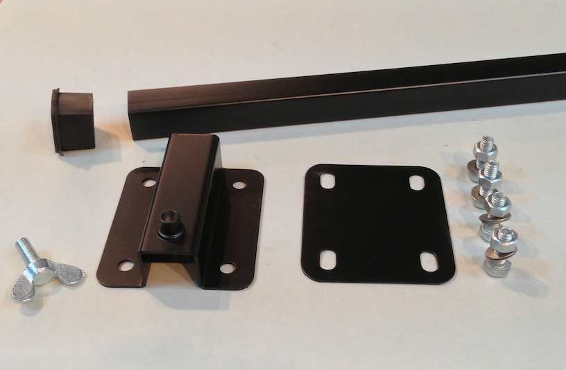
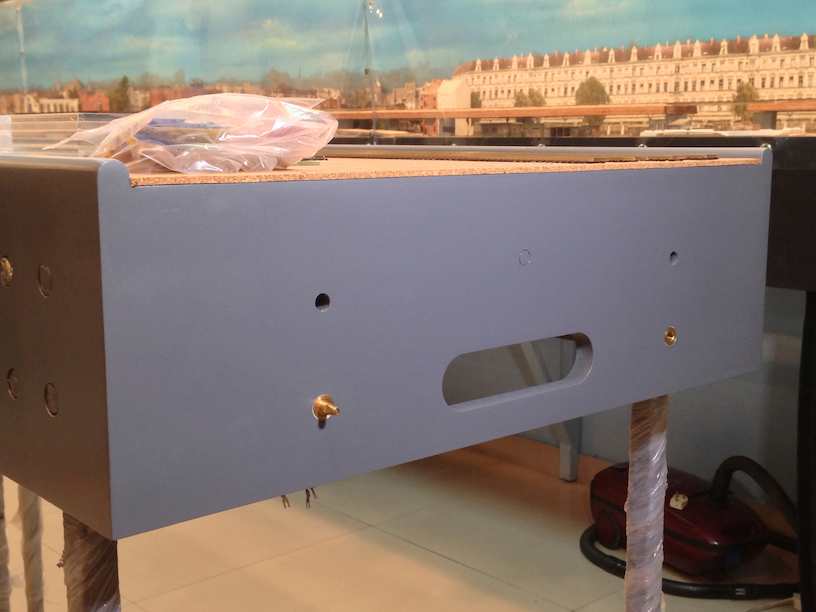
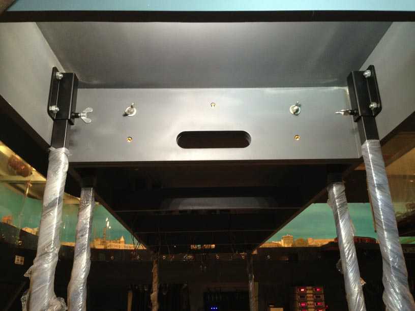
this is how the leg flanges look when installed ……. i left the protective plastic on till later ……
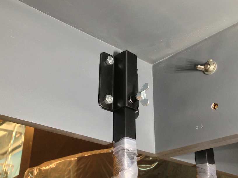
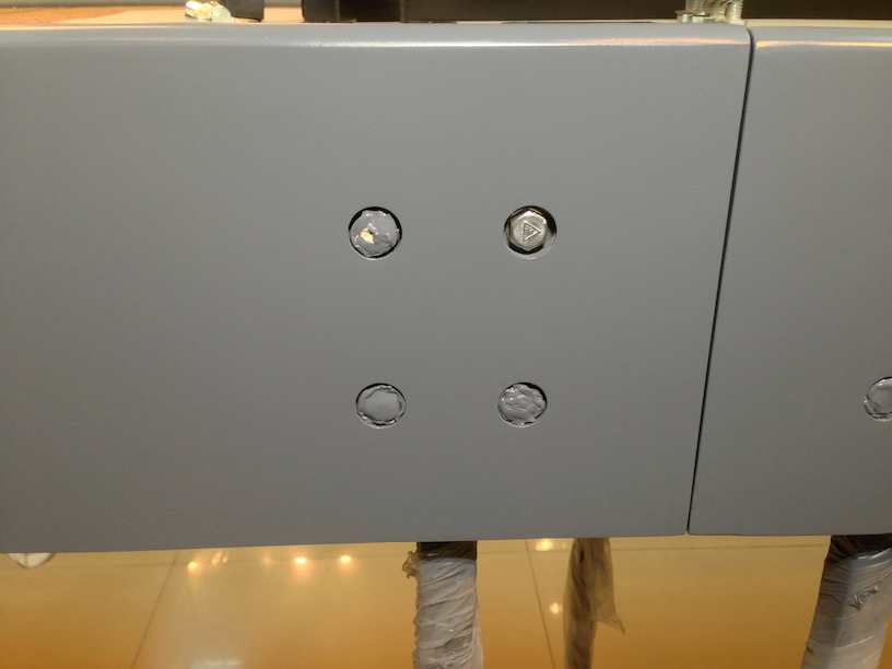
i covered the bolt heads with a liquid rubber mask during the painting process , u can see one bolt head with the mask removed in the pic below. I need to figure out how to cover these bolts …. maybe a laser cut ring or then a plate covering all four together ……
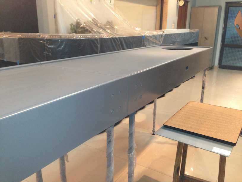
Finally this is how the modules turned out …..
and from below ….
next in the series….laying cork
previous in the series …..initial plan
Hi, this is the web page – http://www.modulbahner.de/FREMO-FLANSCHE/index.shtml. It is in German so you will have to translate it – google translate does a pretty good job. I bought this quite a few years back …. hope it is still in production !!
Hi Vikas
could you please forward me Heiko Meyers e-mail address I would like to order the leg holding flanges from him.
regards
Doug