I always enjoy wiring up a model railway layout and back myself to do a neat & clean install , duly documented and labeled to a high extent so as to make future trouble shooting easy. The Fremo staging yard modules presented the perfect opportunity to further hone my wiring skills …..With that in mind I first drew up a wiring plan in Adobe Illustrator. I took the time to also draw up illustrations to represent the various components I was using …. this was quite tedious and time consuming to do …I made two plans …..
One for the left side……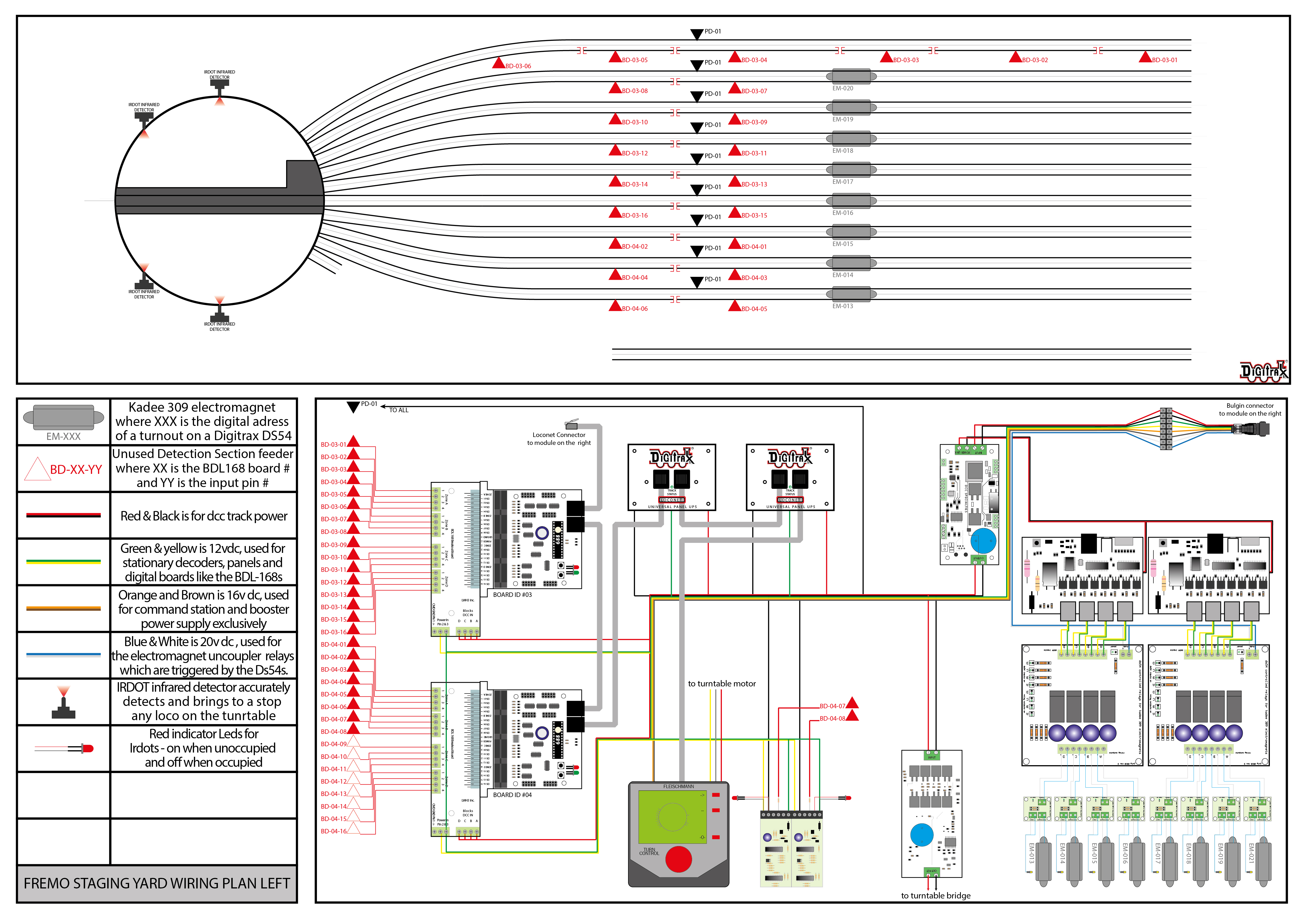 click on pic
and one for the right side……..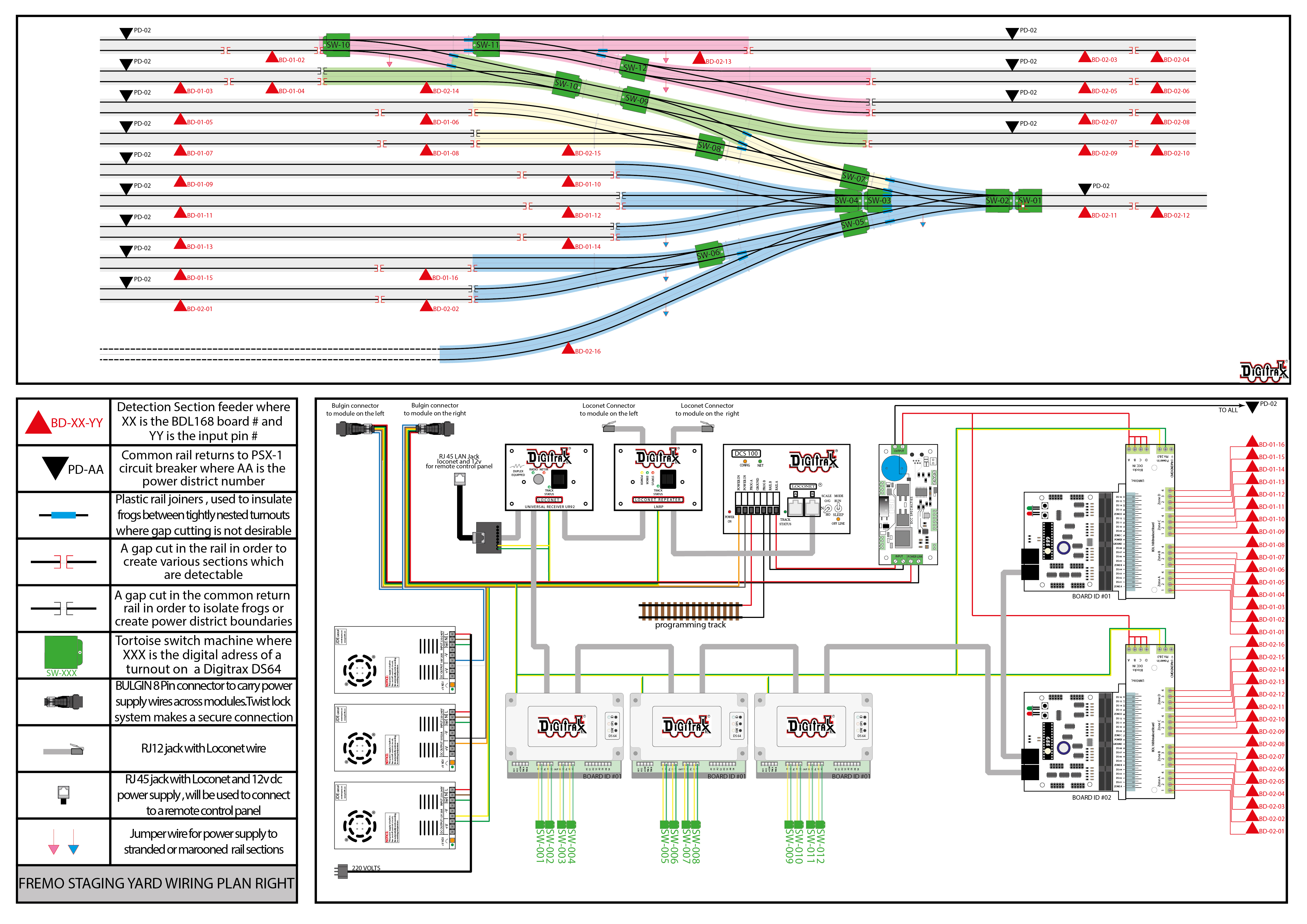 click on pic
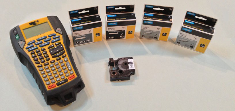
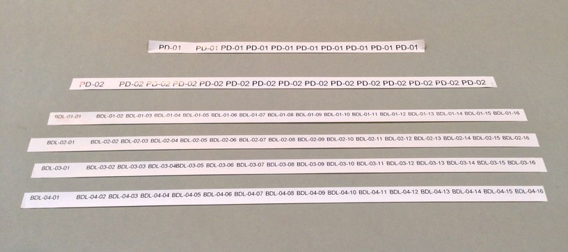
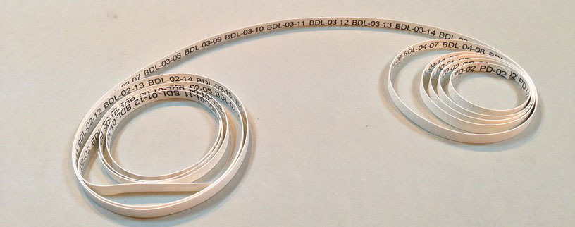
Planning ahead helped a lot as i could pre-print all the markings and identifications i needed. I used the Rhino 6000 label printer to print out various labels in vinyl and also printed heat shrink tubes which i could use to identify and insulate the wires …..
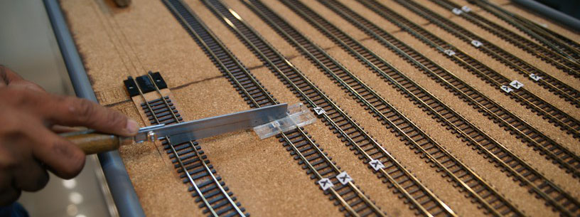
I next cut all the gaps in the track which were needed to isolate the turnout frogs as well as those which would be needed to form the detection sections. The pre-planned wiring chart was a great help in this as i did not have to rack my brain whilst physically cutting the gaps which can lead to mistakes …… “X” marks the spot !!!
I then took some 0.5mm plastic and cut thin strips about 3 inches in length. Inserting them into the gaps, i secured them using chloroform …
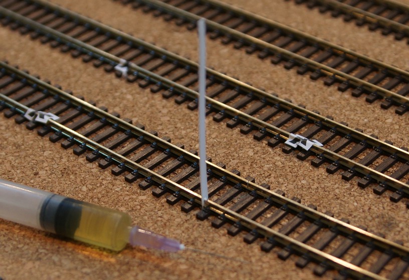
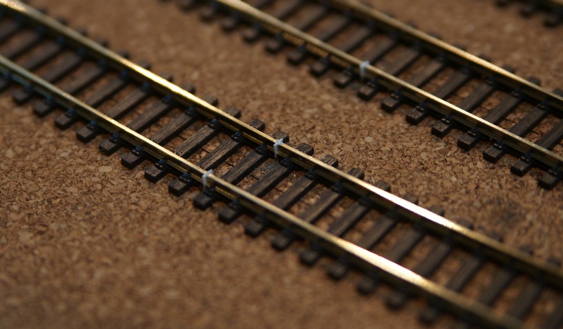
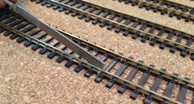
After the plastic was secured, i cut the excess length and filed the plastic down .Once painted the gap would all but disappear. This is an important step because if left open, the cut in the track could close due to temperature variations and cause false detections. In case it was a gap cut to isolate a frog then we would have a short . If the track is painted and ballasted these gaps are a bitch to locate and fix …. guess how i know !!!
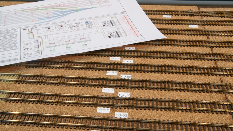
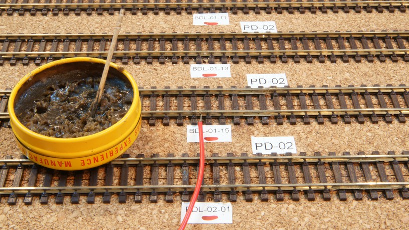
Using the wiring plan as a guide, i put down all the labels i had printed earlier in their designated locations. This will greatly speed up the wiring, reduce the chances of mistakes and be a god-send when i set-up the computer programming for automatic operations at a later stage ……
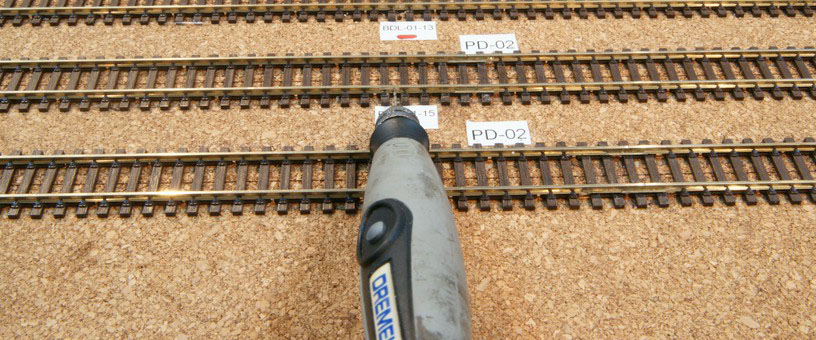
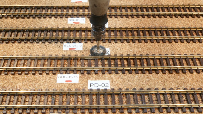
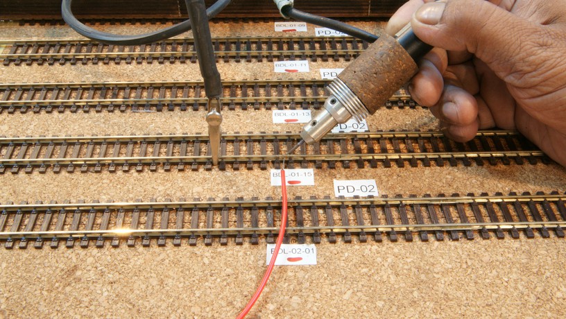
I then start wiring up the different detection sections by first drilling a 1.5mm hole in the track, then cleaning the area with a wire brush loaded in a dremel , applying flux and then using the resistance soldering method to solder the track…
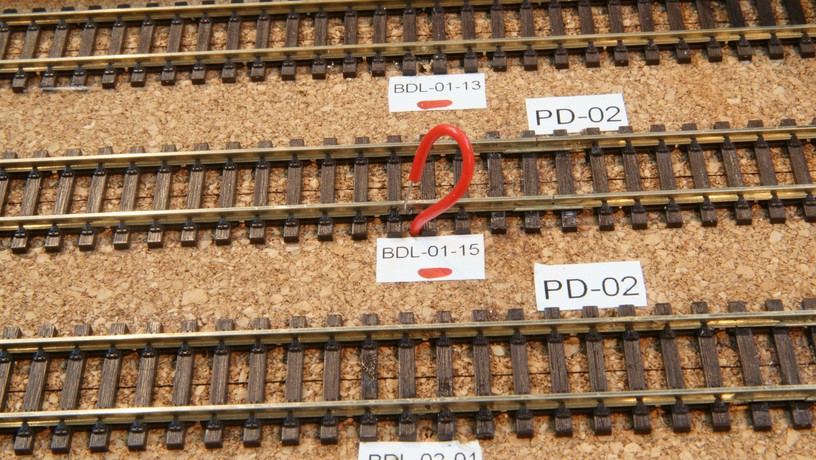
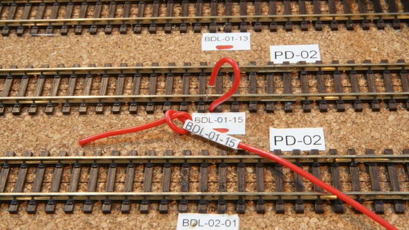
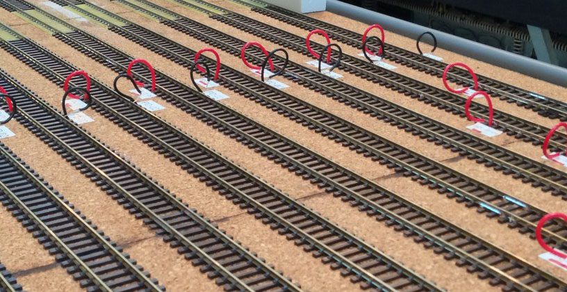
After drilling a 2mm hole at the relevant position i insert the wire thru the hole leaving just a little loop at the end so that i know this section has been done . If i pull it in fully the wire disappears and causes a lot of uncertainty and confusion on whether or not the wiring in that particular detection section has been done or not ….
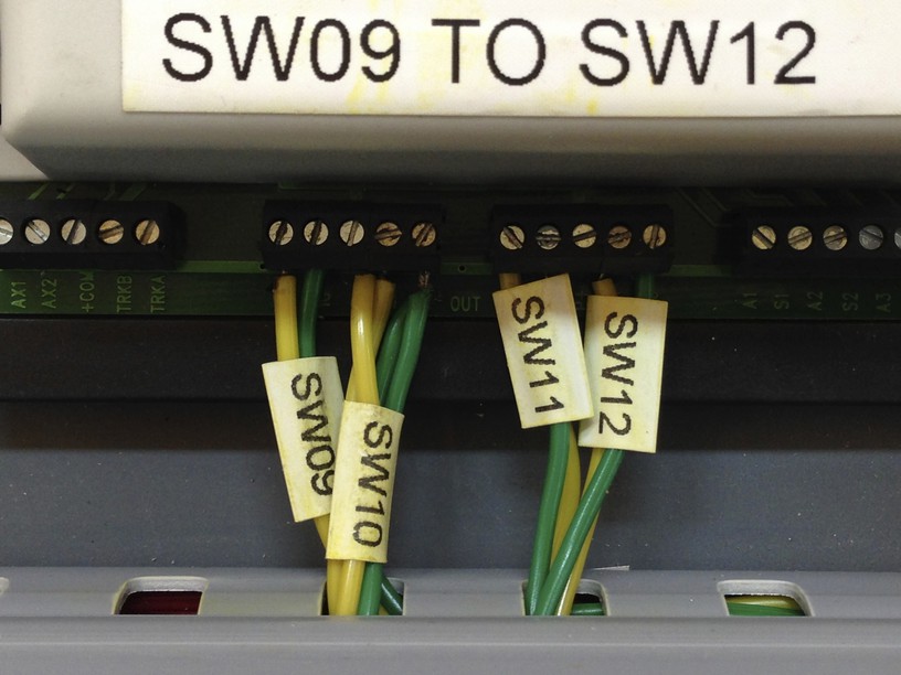
at this point , i also reach down below the baseboard and at the other end of the wire i slip on the relevant printed heat shrink tube and ensure it does not slip out again by tying a knot at its end ….. later on when installing the wire in the detection board these printed heat shrink tubes will greatly simplify the wiring which can all to easily be done incorrectly ……..
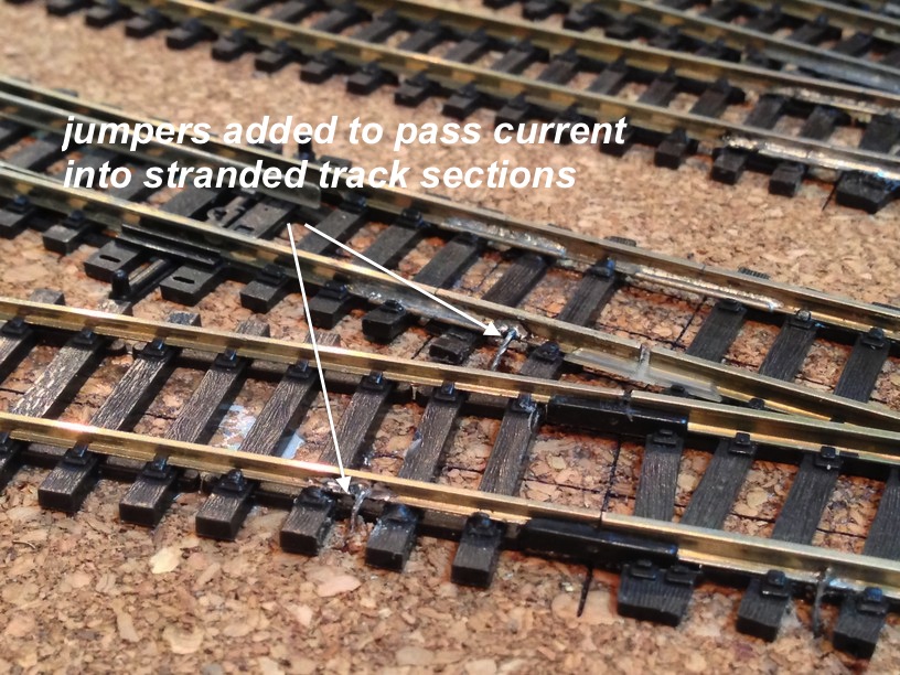
During the planning stage i noticed that there were certain small sections of track which had got “marooned” or “stranded” due to the cutting of gaps and had no wires feeding them. I simply attached some jumpers to the adjacent rails which were live and ensured there were no dead spots ……
Bit by bit , i covered all the sections of track and finally reached a stage when all were done …….
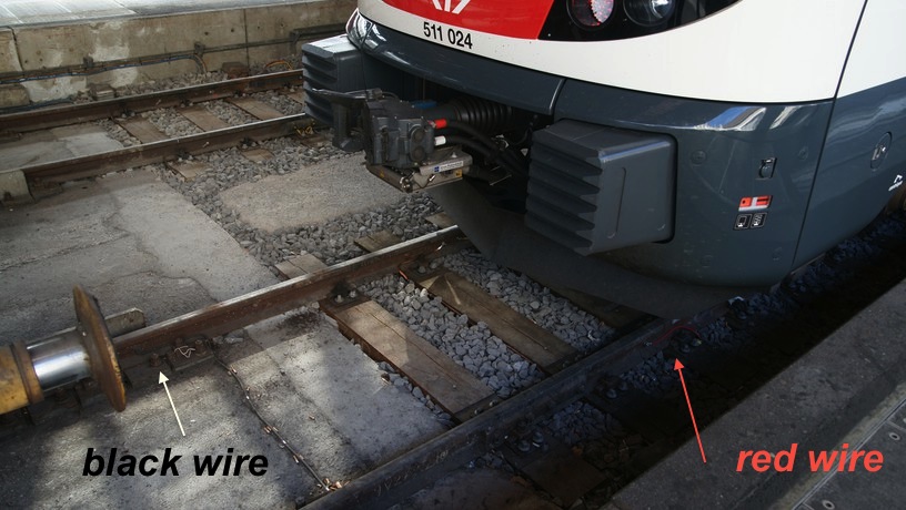
On a recent visit to Zurich main station i noticed the Swiss Railways were also copying my methods of drilling holes in tracks and attaching feeders and detection sections ……. and using the same red and black wire color coding….
I also took the trouble to color code the wires as per what I intended to use …
- Red & Black for the DCC track power,
- Green & Yellow for 12v DC for the Boards,Panels and other assc,
- Orange & Brown for 16v DC for Command Stations & Boosters,
- Blue & White for 18v DC for electromagnetic uncouplers
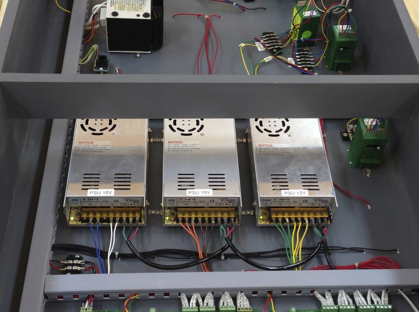
I first installed the three power supplies which were 12v, 15v & 18vdc. They have voltage adjustment pots and I cranked up the 15v to 16.5v and the 18v to 20v just to have a little more “oomph”.
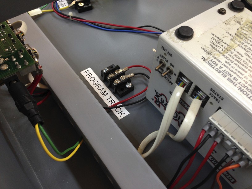
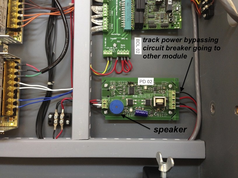
I then proceeded to install the command station and whilst at it I also added a terminal block for the programming track . I have yet to install a programming track and I may or may not do this in the future …. Next I put in the DCC Specialties PSX-1 circuit breaker after installing a speaker into it so that I could get audible reference in case of a short. The other set of wires seen leaving the PSX-1 is bypassing the circuit breakers and will connect to other modules ……
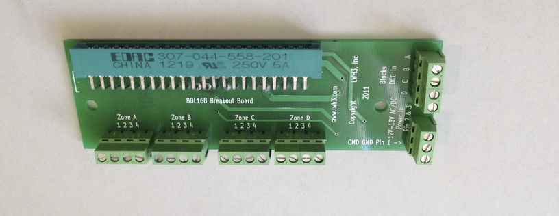
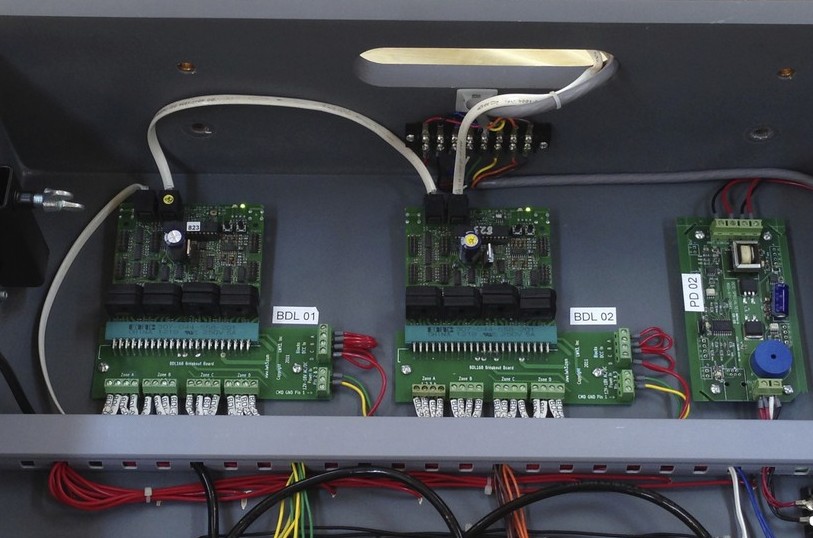
The block detection boards – Digitrax BDL-168s – were installed using breakout PCBs to make the wiring easier……
The digitrax Ds-64 stationary decoder for controlling the tortoises came next…
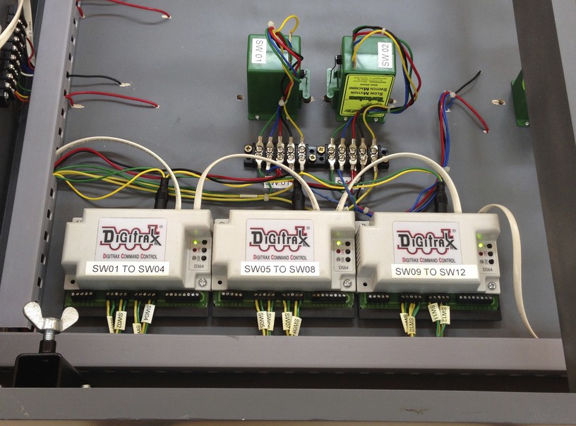
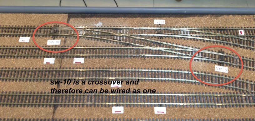
Even though I had 13 switches on the layout I used only 3 DS-64s with 12 outputs as I could wire a crossover using two tortoise machines as one which operate in tandem. This was switch # 10…..
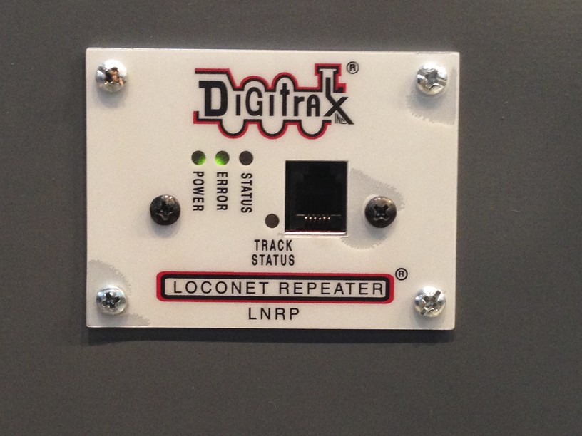
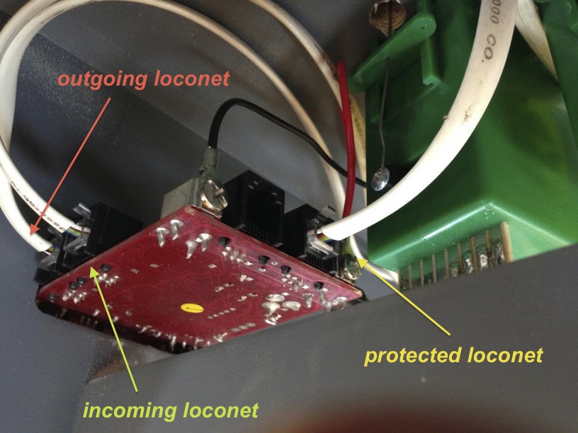
Next came the installation of the Digitrax UR92 radio panel and the Digitrax Loconet repeater …. the loconet repeater is an important component in a modular setup and helps isolate a module group with faulty loconet wiring from the rest of the module groups.. I hooked up the green/yellow 12v power supply and the red/black DCC track power as per requirement. The loconet cables we see in the pics were installed later…..
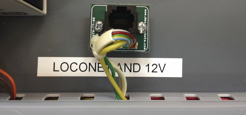
Next up a little bit of innovation, I took a RJ45 breakout Pcb and installed it near the command station. I stripped a loconet cable and soldered the 6 wires to the breakout pcb. The remaining two poles were then hooked up to the green/yellow 12v supply. Later on I intend to make a route control board with the CML electronics DTM-30 and since it needs a 12v supply and a loconet cable to communicate, I figure I will use this single wire RJ 45 connection to supply it instead of a separate loconet and power supply cable……..
Now I needed to install all the loconet cables . Here are the compnents needed , RJ12 jacks , good quality of non-shielded 6 core flat telephone cable and a crimping tool…
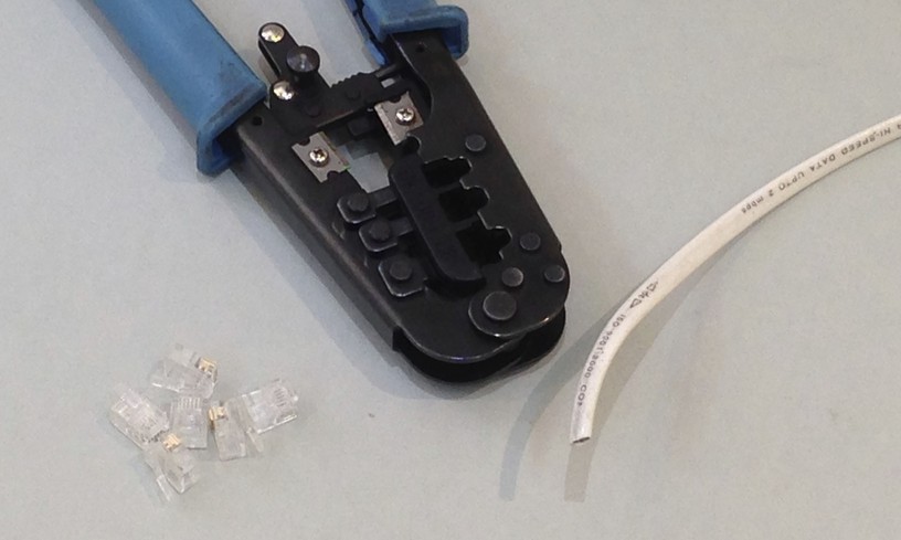
… first cut and strip the wire to length ….. the crimping tool does the cutting and stripping in one go ….
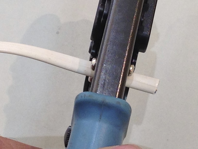
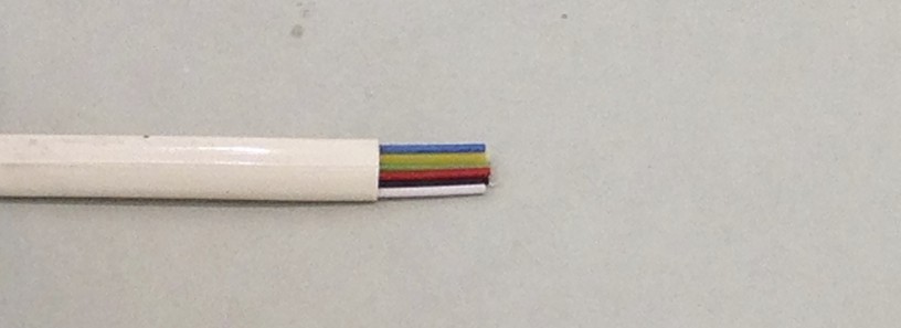
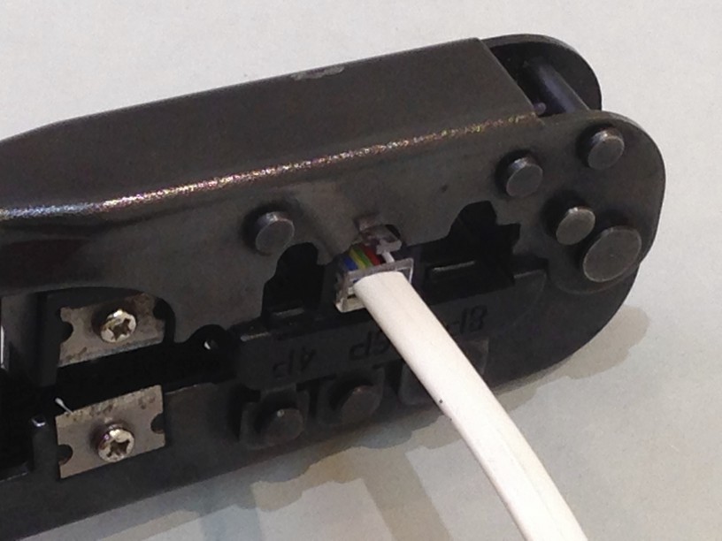
next insert the Rj12 jack into the crimping orifice and introduce the wire into the slot of the jack while ensuring polarity is maintained …. i simply follow the mantra ” white on the right “…..
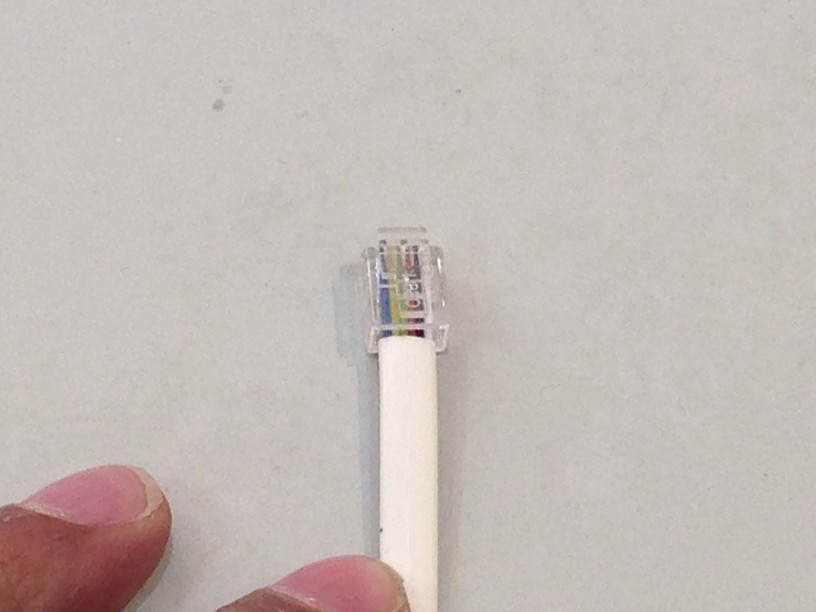
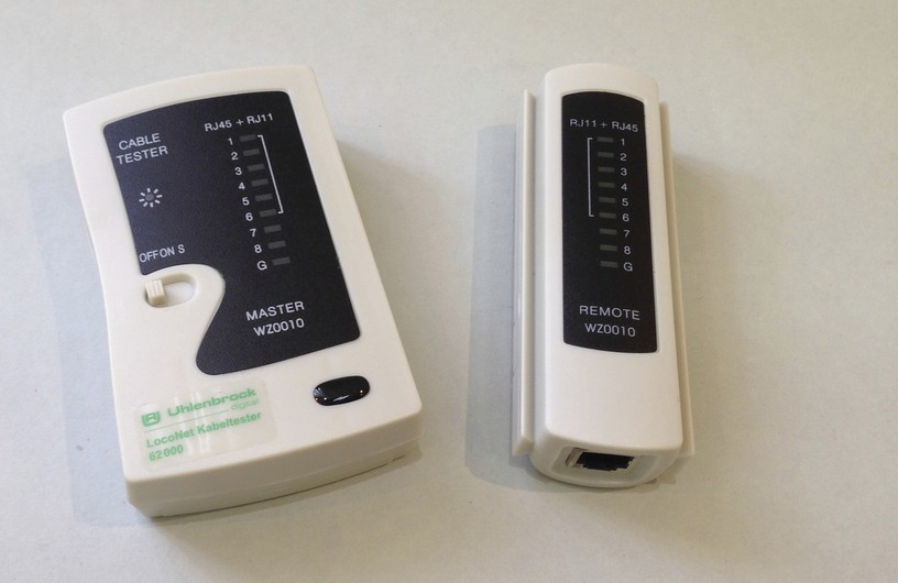
next test the cable using either an Uhlenbrock tester or the Digitrax supplied loconet tester …. both work well ….. voila !!! ….. our loconet cables are ready to go …..
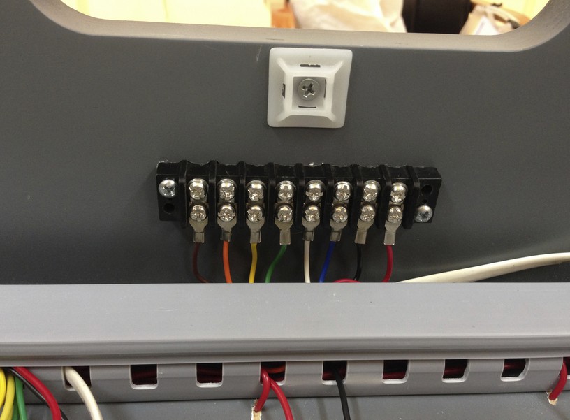
Finally I installed two eight pole terminal boards at both ends of the modules and hooked up an eight core cable with the correct wire colors to the power supplies and also the DCC track power ……. as you can see the color coded wires are as per the wiring plan nomenclature and each carries the specified voltages…..as the number of modules grow i expect this discipline to be of immense value …..
To transfer the different voltages across modules i chose 8-way connectors from Bulgin…
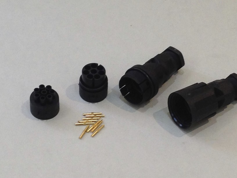
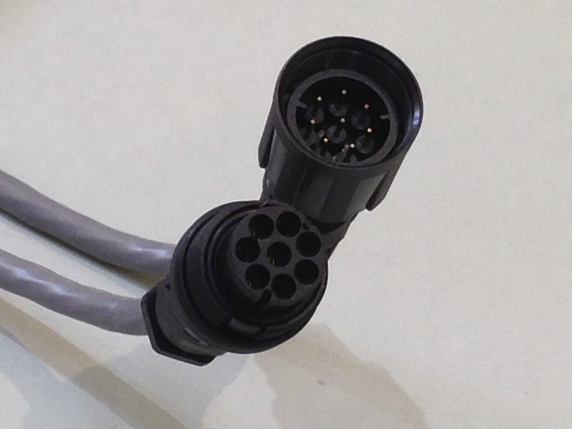
they are easy to connect between modules and are very reliable …. i also connect the loconet wires using a RJ12 “both side female” adapter …..
I then turned my attention to the other module, the left side …. which was relatively easier to do. I put in the Dcc specialties PSX-1 and the Digitrax detection board based on the same principles as the right side module.
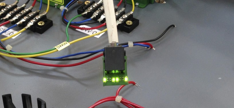
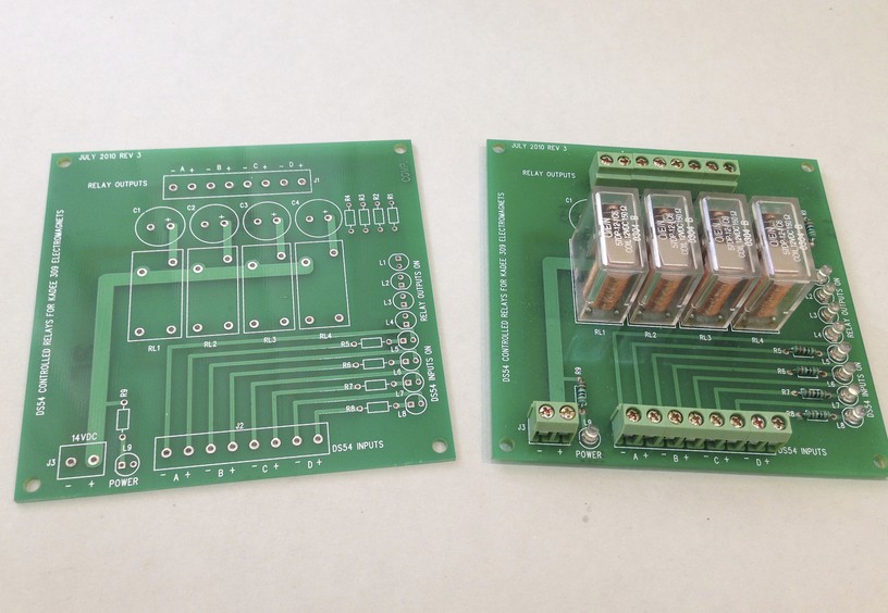
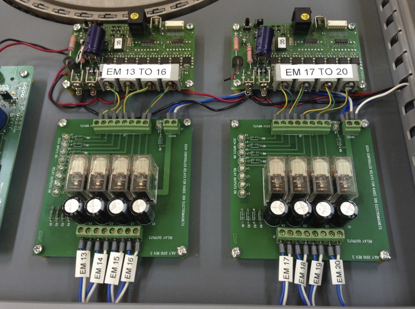
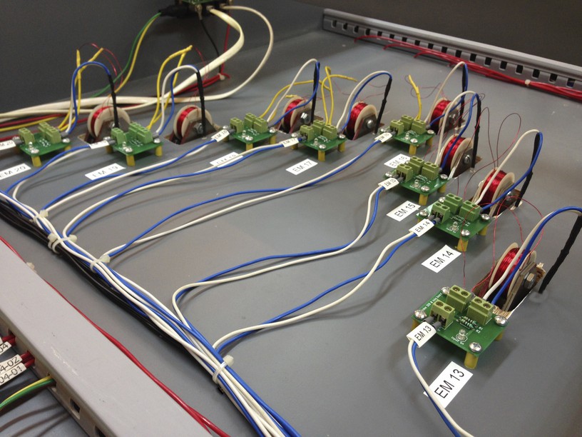
There were 8 electromagnets which I had installed earlier – see post – Kadee 309s install... I wanted to control these via DCC so that I could have automatic uncoupling to go with the automatic operations I had in mind for this staging yard. I connected the outputs of the Digitrax DS54s to a relay since the current draw of the coils of the electromagnet is too high for the DS54s to handle directly. To keep the wiring and connections manageable I designed and custom made a PCB board on which I mounted the relays, capacitors, connectors and Leds….
I programmed the ds54 outputs for continuous output . I also programmed the CVs so that the output would automatically switch off after 10 secs in order to prevent the burning of the electromagnet coil in case I forgot to switch off the current. In case 10 secs was not enough to uncouple , I also made the output re-triggerable , so that another press of the switch command would give me an additional 10 secs and so on … till i either managed to uncouple the wagons or burn the coil …… The relays were fed with blue/white wires at 20v…..
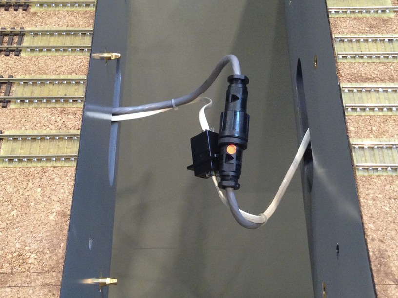
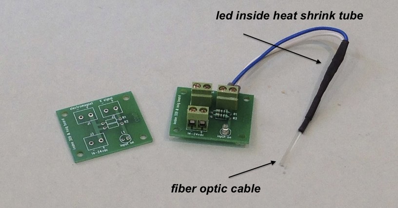
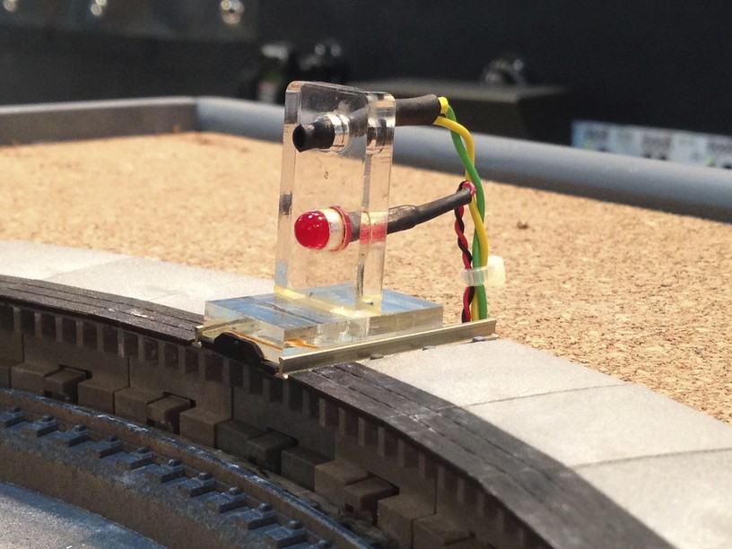
I also designed and custom made a smaller connection board for the electromagnets . This smaller board had a power on led as well as outputs for the electromagnet and an additional LED…..to which I connect another LED with a 2mm fiber optic cable heat shrunk on to it. A hole drilled next to the electromagnet would carry the light thru the fiber optic top side right next to the track and relevant electromagnet. Now firing the electromagnet would give me visual indication that the electromagnet was in play. In a darkened room it would also be easy to spot its exact location. ….
also have a look at this short video where one can see the electromagnets at play …..
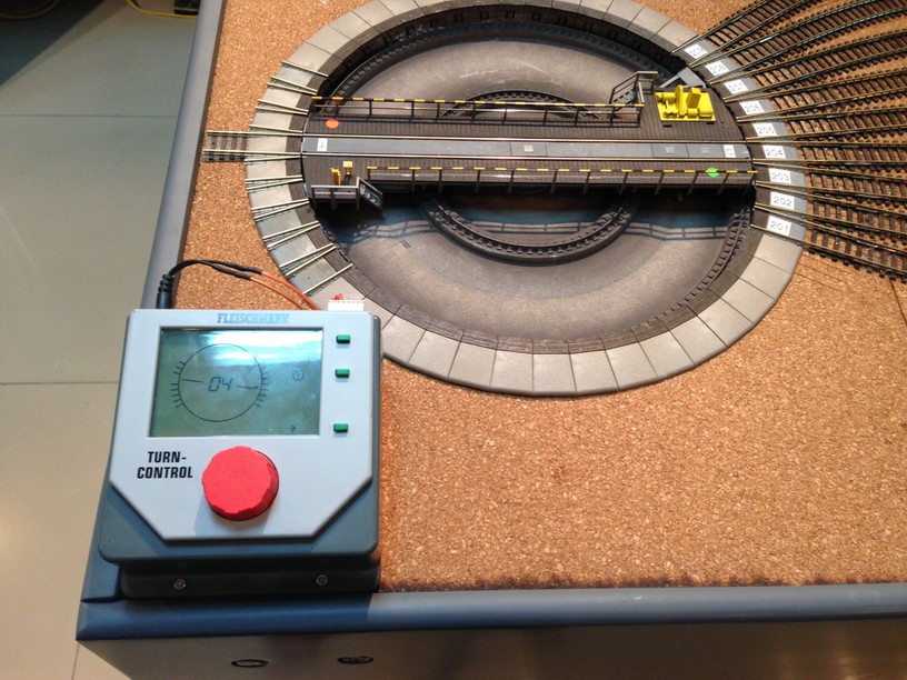
Turning my attention to the already installed Fleischmann 6152 turntable , I installed the Fleischmann Turn-Control which allows automatic indexing of the turntable thru loconet commands . This will be essential to the computer control of the staging yard as we will see in a future post……
But we need to deal with the small matter of how to bring the loco to a stop on the bridge and ensuring it would not over or under shoot …. I had previously tried detecting the bridge track but that did not work reliably as locos with different lengths would stop at different locations. So the solution I have now is detection thru the Irdots – basically an infra red detection board which triggers relays depending on whether the infra red detection has been triggered or not ……. i install a set of irdots at the center axis of the turntable , a second set i install just short of the end of the turntable bridge …… the one in the center could serve as a braking and virtual stop section and the one which is 3 -4 cms short of the end of the bridge track , would serve as the absolute stop location if needed for certain longer locos . We will see when we set up for automatic operation how these IRDOT sections come into play ….. because to understand what i am saying above is only possible if one has worked with the computer control software – Railroad & co……
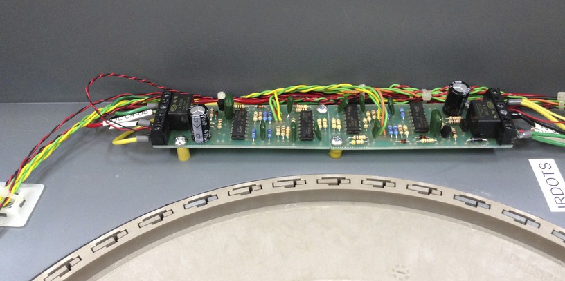
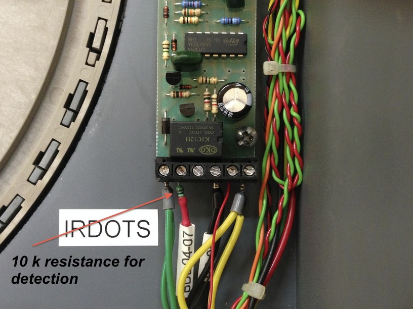
The IRDOTS work on the principle that a beam when emitted and read back after reflection from the under side of any rolling stock covering it, deems the section as occupied. Once the rolling stock moves away there is no reflection and the section is now unoccupied . In both states a relay is triggered and a circuit completed. In my case the principle is reversed and the emitter and reader face each other and therefore we always have the situation as “occupied” . Only when a loco comes on the bridge and blocks the emitting and reading of the infra red beams is the situation reversed. The relay which is triggered in this “unoccupied but actually occupied ” situation is wired with a 10k resistor to a detection section of the Digitrax BDL-168 and it now “detects” the loco to be on the bridge track…..a little difficult to explain coherently i guess but easy to implement none the less ….
Here is a short video of the turntable indexing and Irdots in action ….
That completes our electrical wiring of the modular staging yard and in the next couple of weeks I might further fine tune it and test it thoroughly before setting it up for automatic operations which should be fun to do as well. If you are reading thus far, then hats off to either your patience or your interest …. !!!