My previous layout had about 80 points all fired by solenoids switch machines from Peco and Hornby. In retrospect they were quite difficult to install involving a lot of ugly cutting and jigsawing ……..
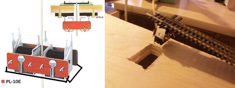
Post installation they did not always operate reliably resulting in a lot of misfires. I was using a computer software – RR&Co. to control the layout and these misfires would lead the trains into wrong tracks resulting in a lot of derailments , crashes and runaways. One fine day i took the plunge and converted all of the solenoids to tortoises which was no mean task . Ever since , and now 8 years later i swear by the tortoise …….. They have been around for a while now and are in use on many layouts around the world thanks to their robsutness , reliability and ease of installation which is what we will deal with here ….
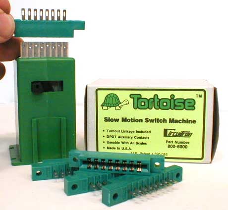
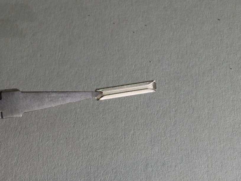
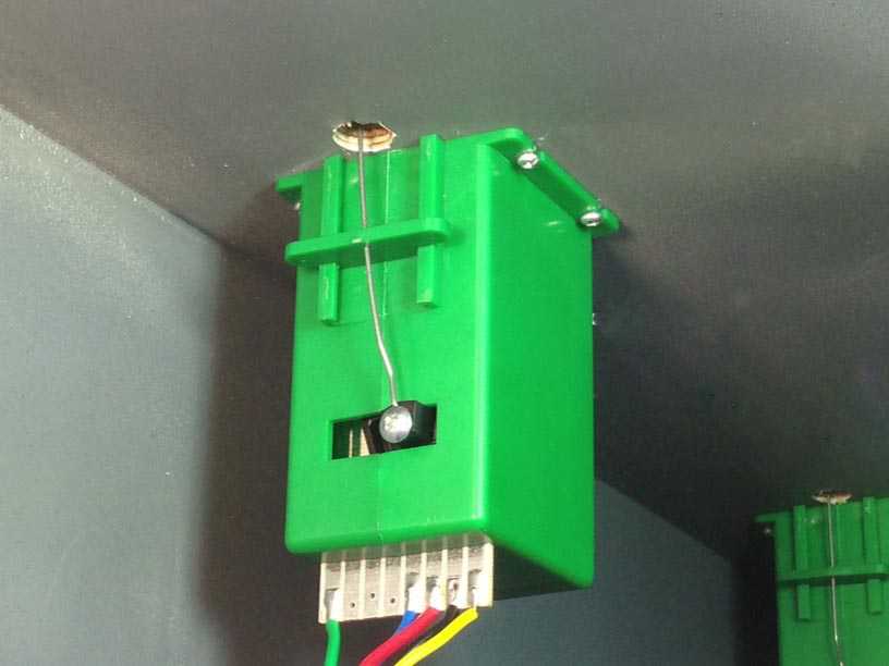
Beneath the hood this is what they look like …… a simple design …
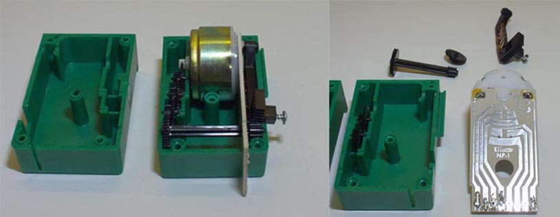
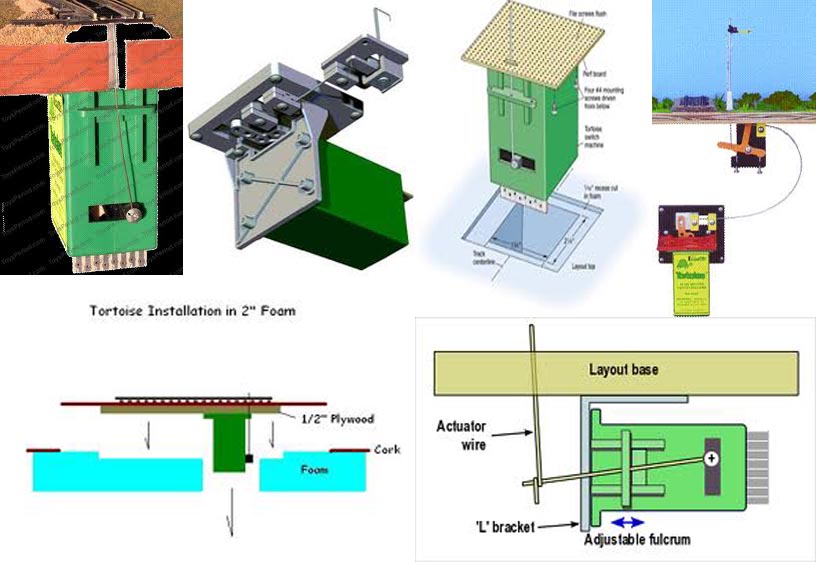
which can be installed in a manner of ways, in different base materials and for different uses ………..
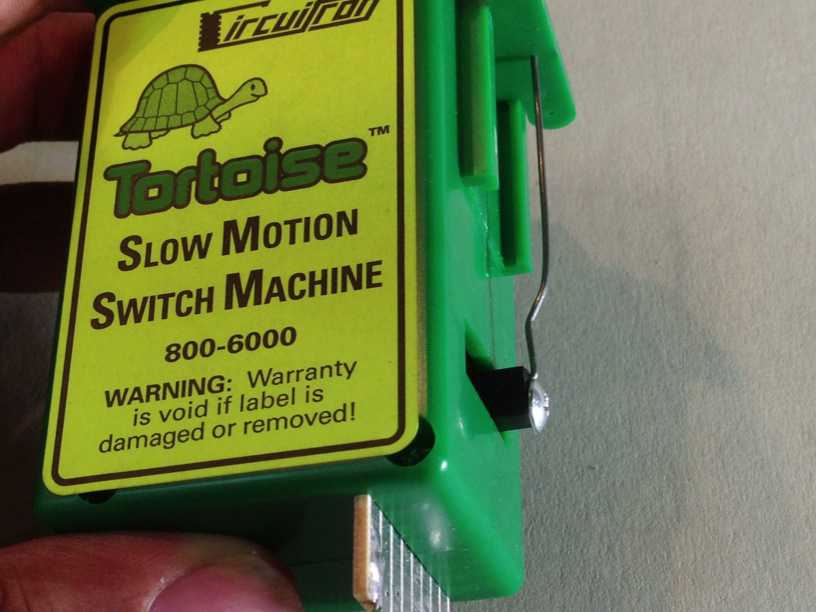
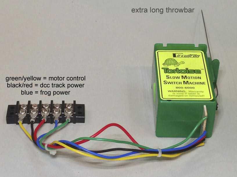
Prior to installation i prep the Tortoises ……first of all i keep an extra long throwbar , apx 6 inches instead of the one which comes packaged with the Tortoise… i find the longer throwbar easier to insert from below into the linkage bar hole ……. i bend the throwbar rod a little differently than what is shown in the instructions which come with the Tortoises . Instead of the one bend suggested i make two bends in the wire This somehow helps to keep the throwbar absolutely perpendicular …..
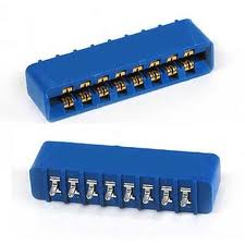
However , my experience with these connectors has not been ideal …… could be i live in hot /dusty/humid India , and that is why i was getting less than desirable electrical continuity through these type of connectors. Anyway , i am quite confident of my soldering skills so i solder the wires directly to the Tortoises……
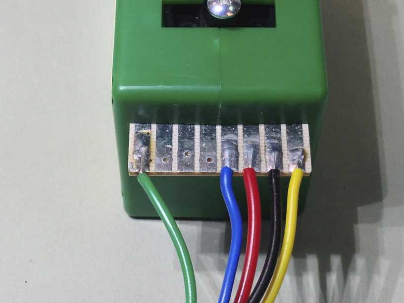
and then connect those wires to a block connector ….. this way even if i have to change some wires around i can do so at the block connector … i also color code the wires for ease of identification and wiring ……
Moving on to the installation itself ,there are a number of jigs out there to aid in the installation of the Tortoises ……
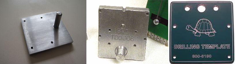
However , while they will help mark out the four retaining drill holes in relation to the throwbar hole , there is no way of telling if it is absolutely square to the track above . If one is not careful, there could be a situation where the installation is improper and the throwbar rod moves in a skewed manner in relation to the point linkage bar ….. this would result in improper throw of the points and possible derailments and at worst exert enough skewed pressure on the linkage bar causing it to break ….to counter this problem i go thru with the process described below ……
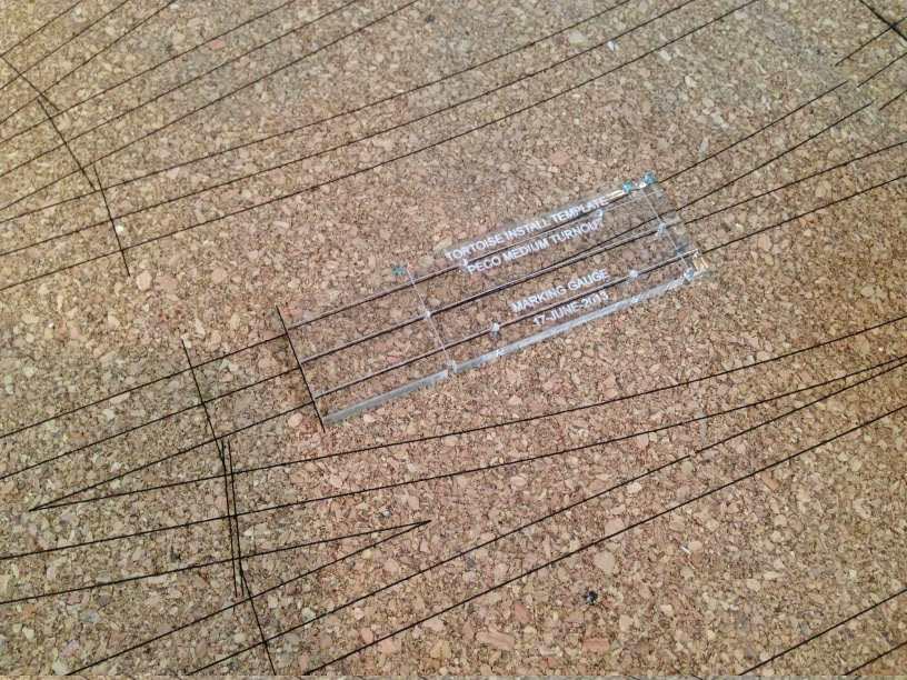
I fabricate out of acrylic, a marking jig on the laser machine . The jig is designed to line up with the turnout end marker line which we had previously engraved on the cork road bed . This gives me the exact location of the throw bar hole without having to locate or measure it for each point. I also engrave the center-line as well the two rail lines at a parallel distance of 8.675 mm from the center-line onto this jig. This makes it easy for me to align the jig correctly to the center-lines and track lines engraved on the cork thus centering everything …..
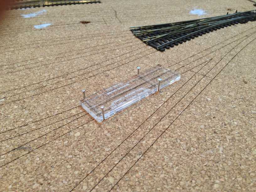
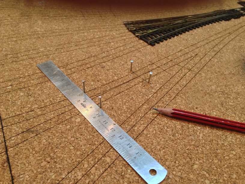
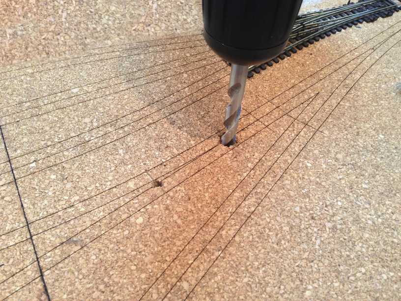
The jig has four notches in which i insert pins/nails and taking a straightedge draw in two lines……… where these lines intersect the center-lines is where i need to drill in the holes ……one for the throw bar and one aligning the bottom tortoise drill hole marker plate ……. i could have made holes in the jig instead of notches but i figured every time i used a drill machine thru the jig it was bound to damage it progressively to the point where the jig was no longer usable …..
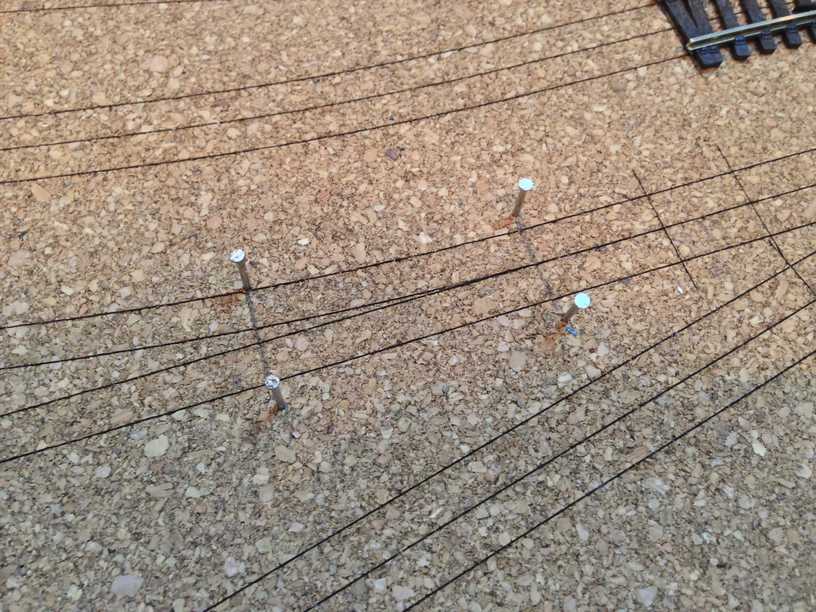
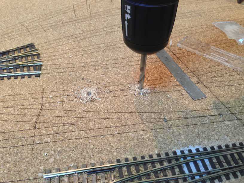
i drill in two 4 mm holes ……
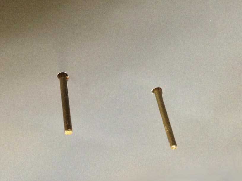
Enter the alignment jig which basically holds two 4mm brass rods of about 20 cms length at the required distances as per the marking jig above …
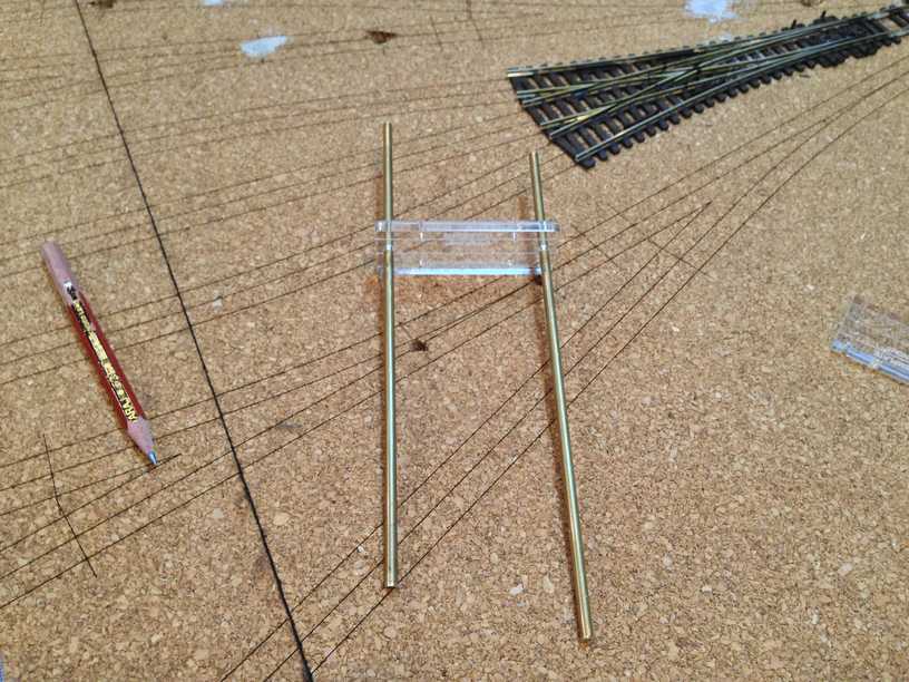
I insert these into the two 4mm holes drilled above …
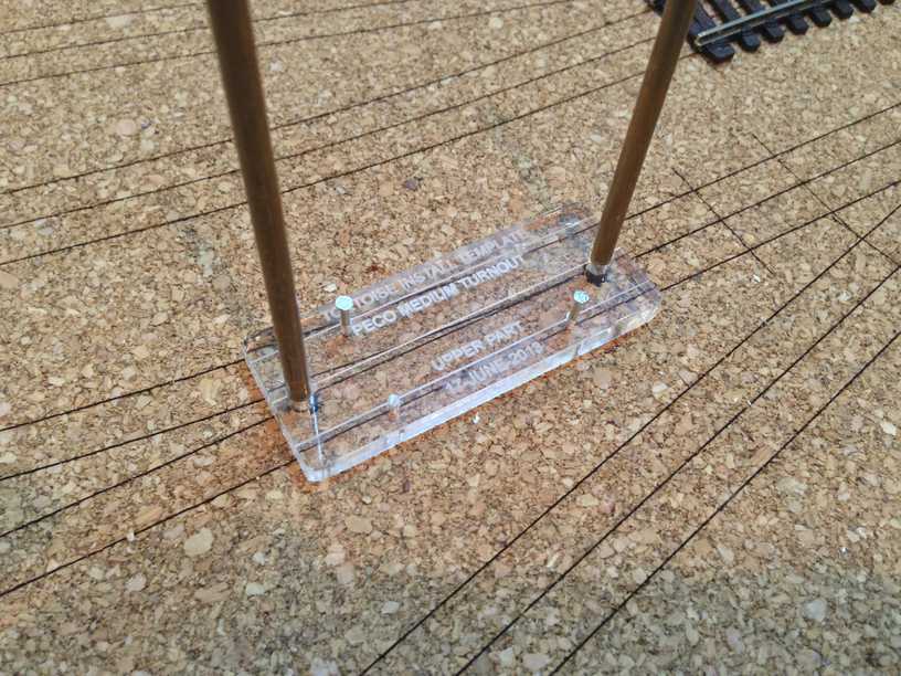
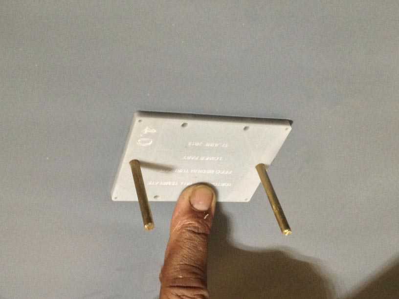
and the same alignment jig brass rods from below..
onto which i slide on the tortoise mounting drill holes template ….
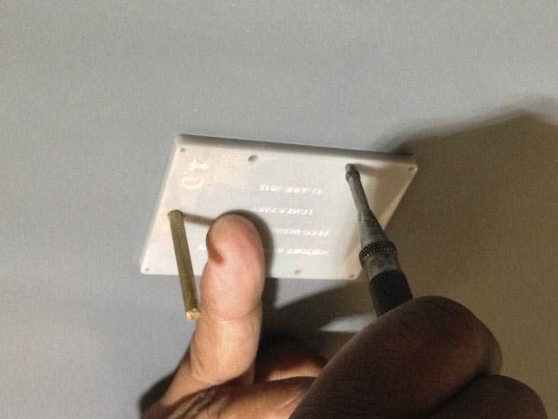
and mark out the drill holes with a spring punch …
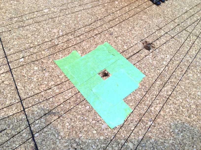
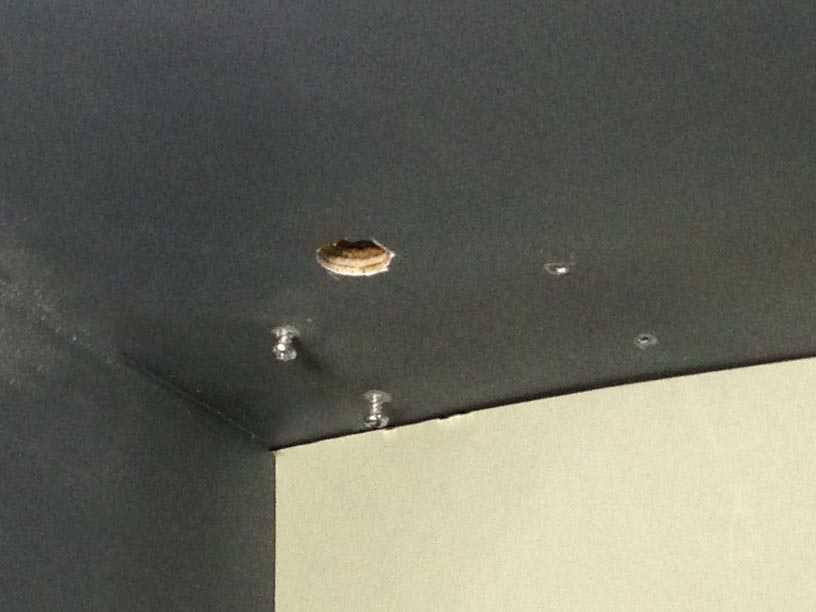
Surfacing again i now expand the 4mm throwbar hole to 10mm ….
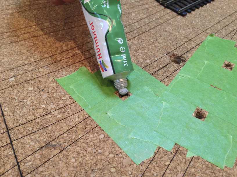
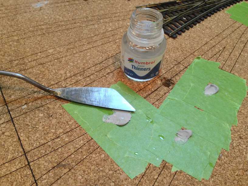
and seal the other hole with a filler from humbrol , taking care to mask the area off so as not to create a mess…
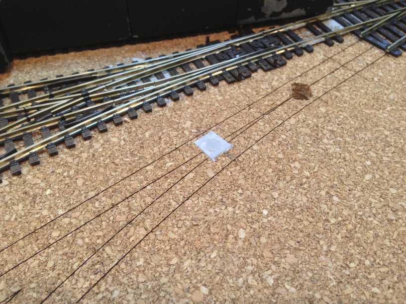
diving down below , i drill in the pilot holes and install two screws first ……..
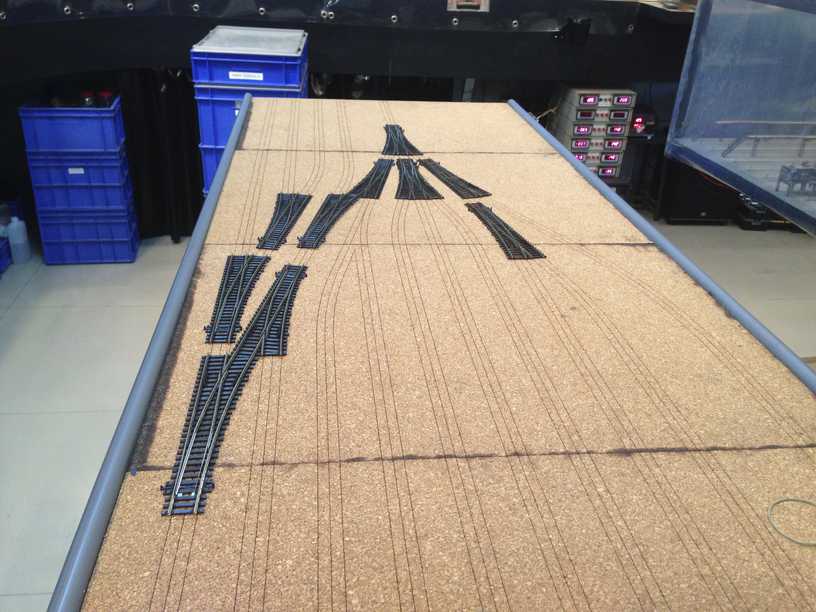
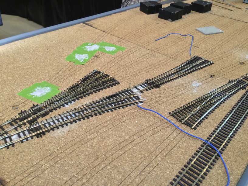
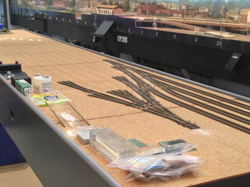
Having followed the above procedure for all the points it is now time to install them …..I lay them out over the engraved cork to check for any flaws …… i need not have bothered as there were none , all the planning and prodding done having paid off ….
Now the points need to be prepped .. an excellent site for learning about the basics of model railway points is Allan Gartners site …. Wiring for DCC ….. it has a wealth of information and very clear explanations to get one’s fundamentals clear ……
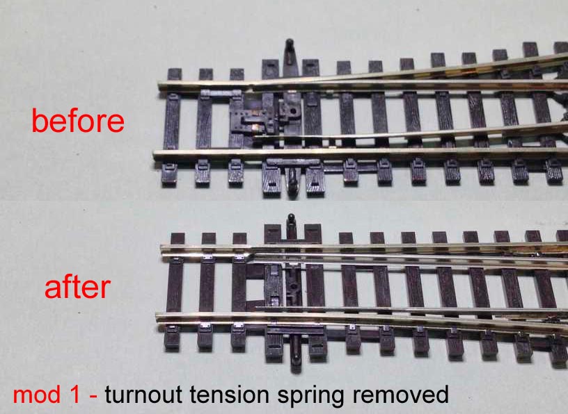
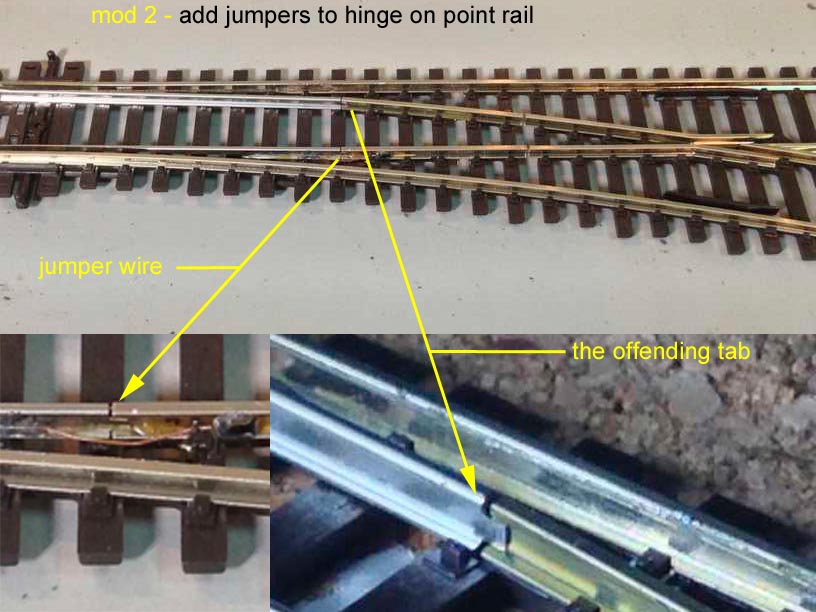
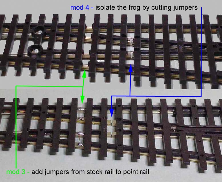
There are five major modifications i make to the peco electrofrog point ………
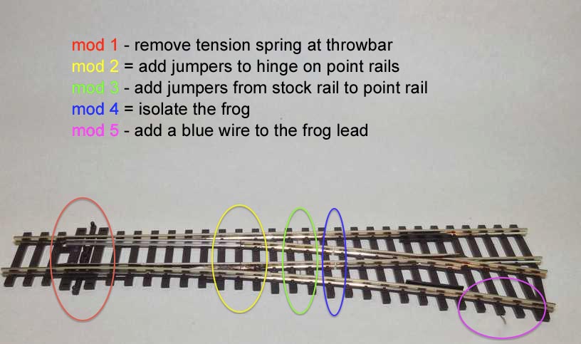
more detailed views of the modifications……
With all the points prepped and the track plan engraved with the rail lines and turnout end markers installing the points itself is a breeze ……
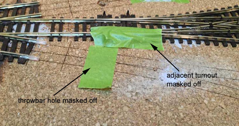
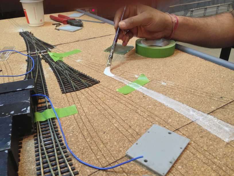
I mask of any adjacent points and also mask off the throwbar hole before white glue application ……..
I brush on the white glue mixed with a little water to help the glue flow/brush easier as well as to stop it from drying up too fast….
and then remove the throwbar hole masking tape …….
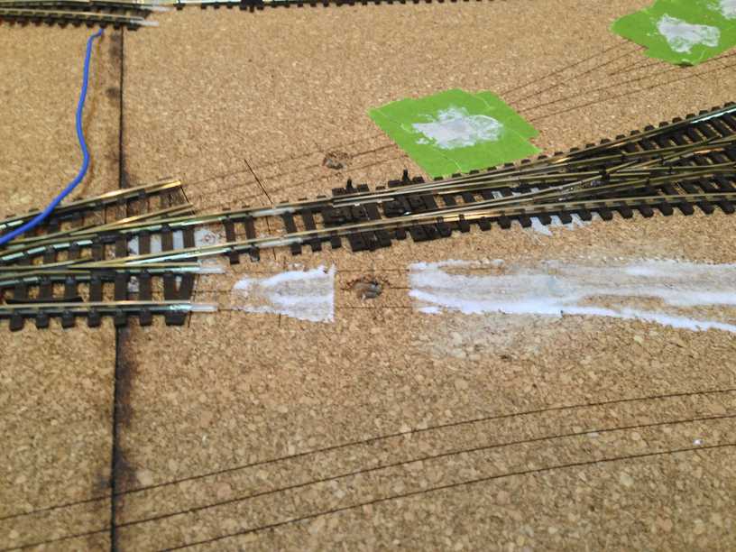
and the point goes into place …..
exact positioning is greatly aided by the turnout end markers and track lines engraved into the cork …..
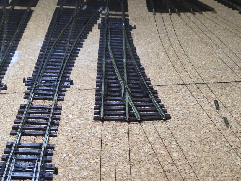
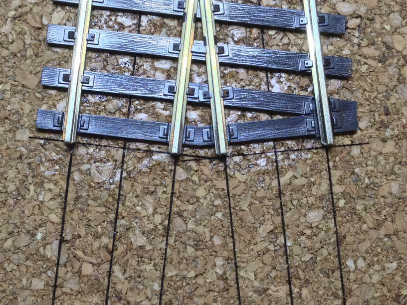
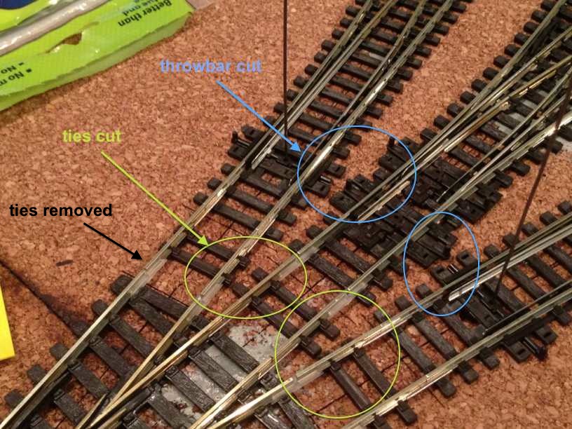
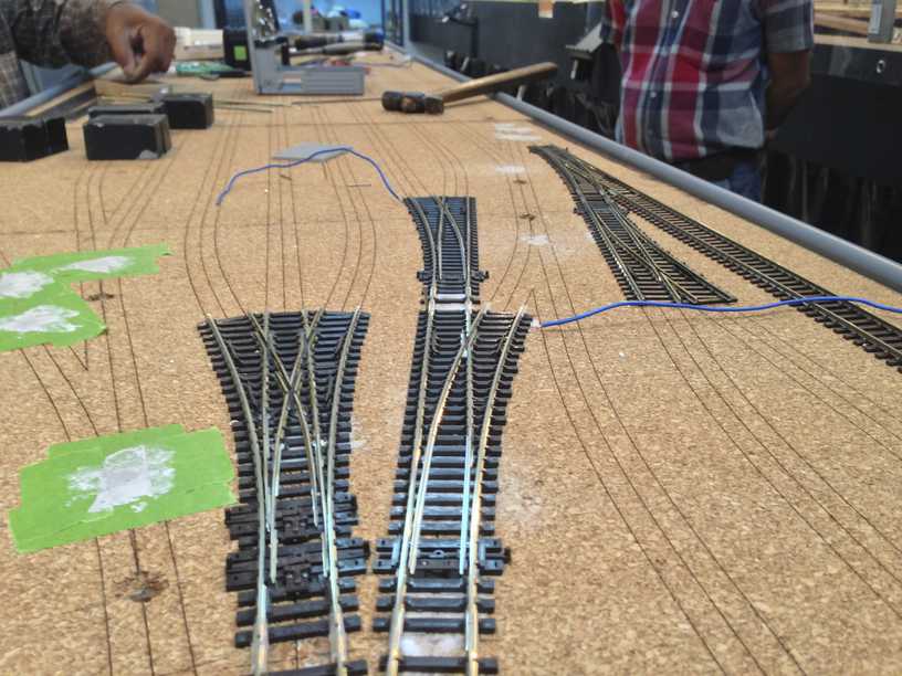
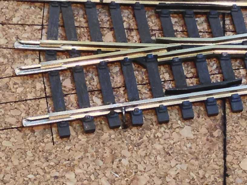
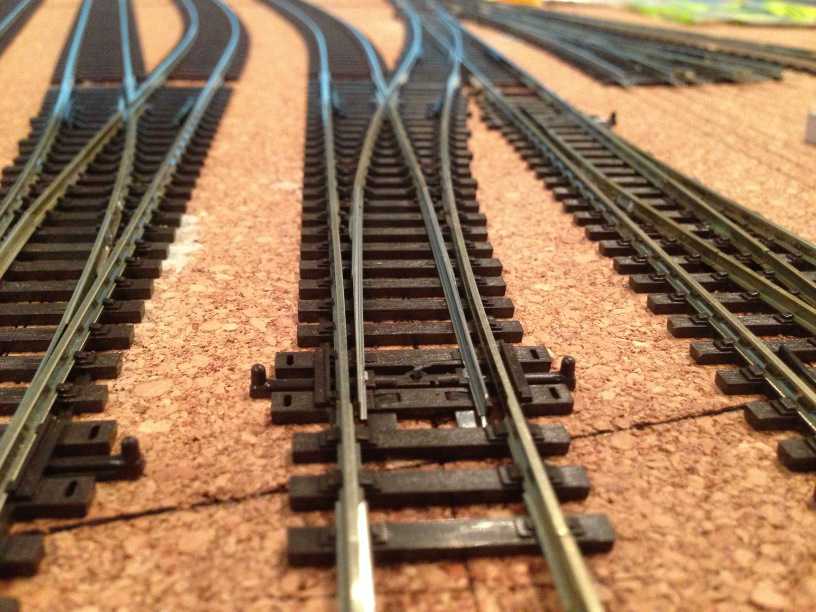
Where the congregation of converging points is concentrated, one needs to indulge in a little bit of surgery …. ties needs to be removed or cut to fit and point linkage bars which can crash into each other while moving need to be trimmed …..
sighting down the points also help align it better ……
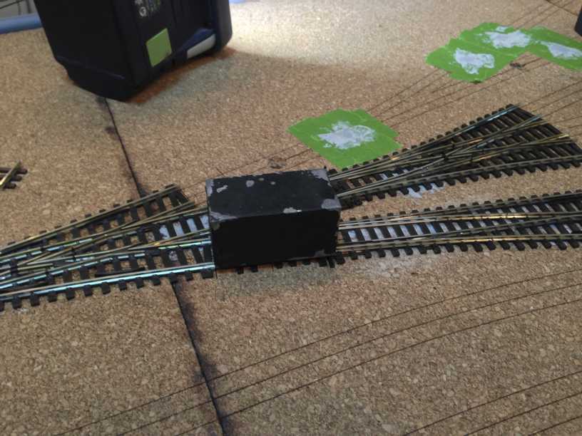
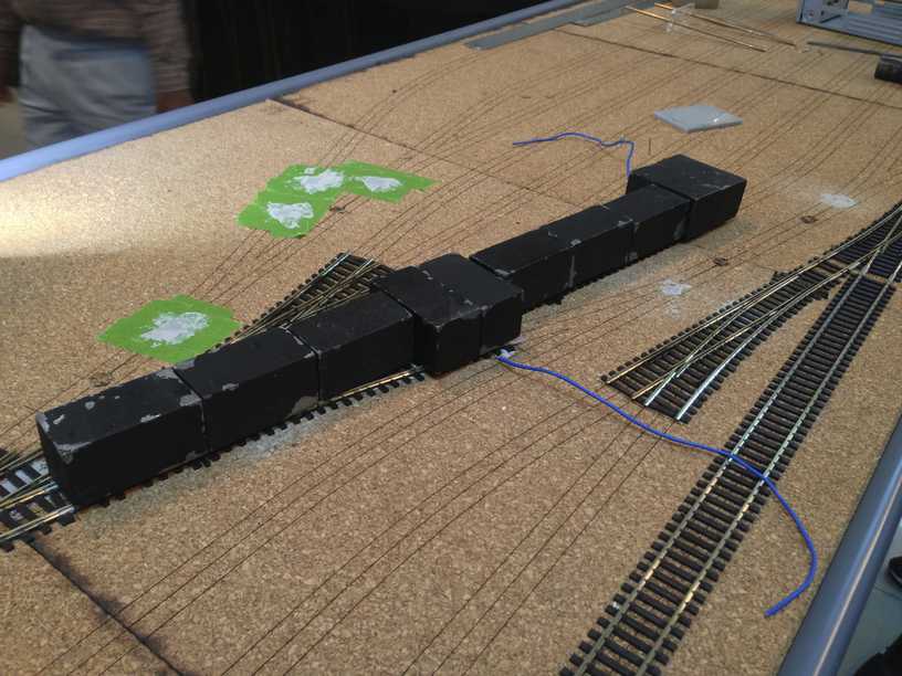
specially fabricated lead blocks , each weighing about 300 grams go onto the points to weigh them down for a few hours …..
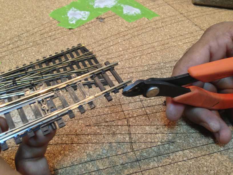
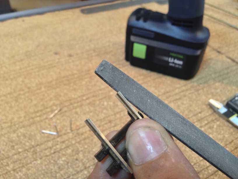
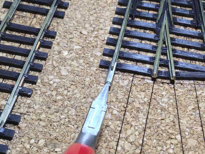
The trusty Xuron track cutter is used to cut the little bits of track needed to fit in between the points. While cutting the track tiny bits and burrs are sometimes left, which i clear off with a Dremel tool loaded with a cut off disk. A flat file is used to smoothen out the shoulder at the bottom of the rail . This helps the rail joiners to slide in easier …..
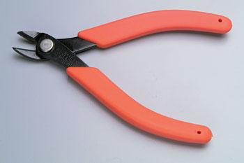
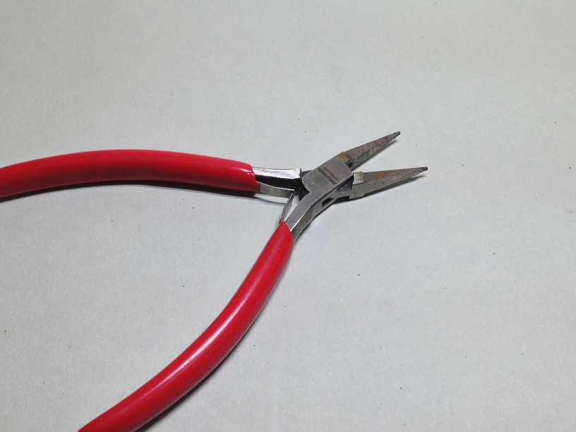
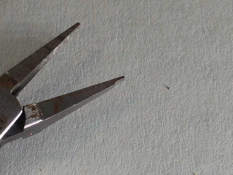
By far the most handy and underrated is the plier to insert rail joiners…… trust me this can be a ” painful and bloody ” process …….. but made easier with this plier from Fohrmann Werkzeuge in Germany ……
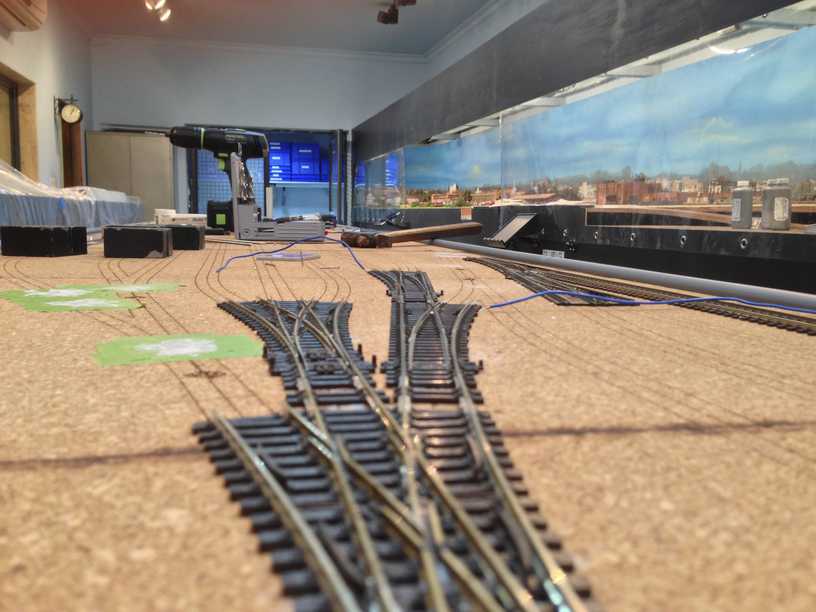
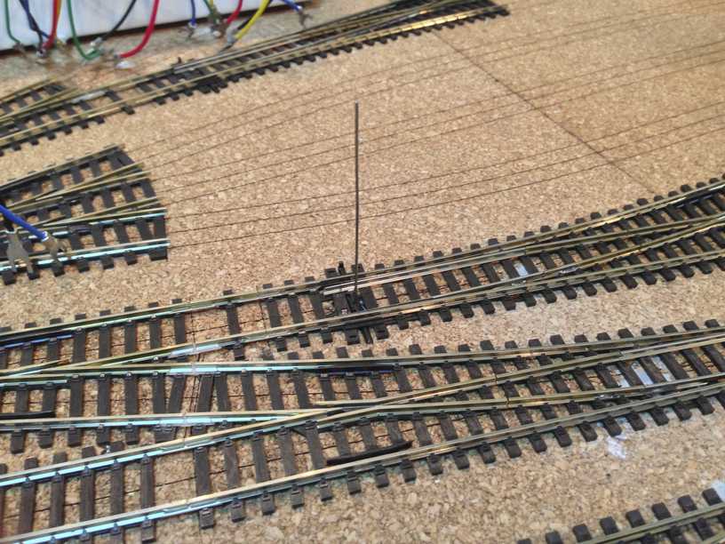
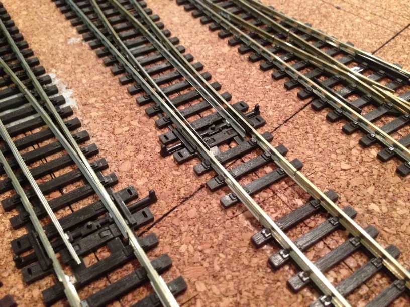
a while later all the points were down ….. including a bit of the track of the annexe area………
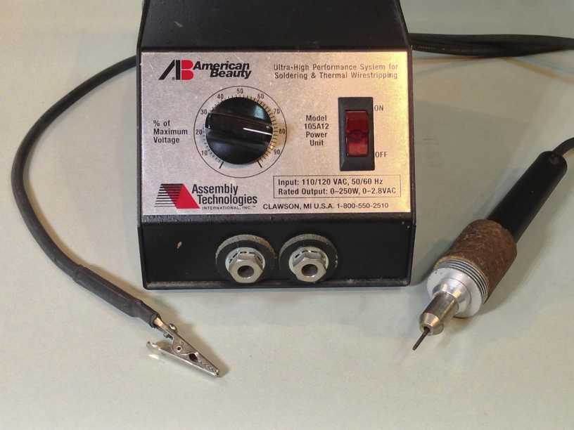
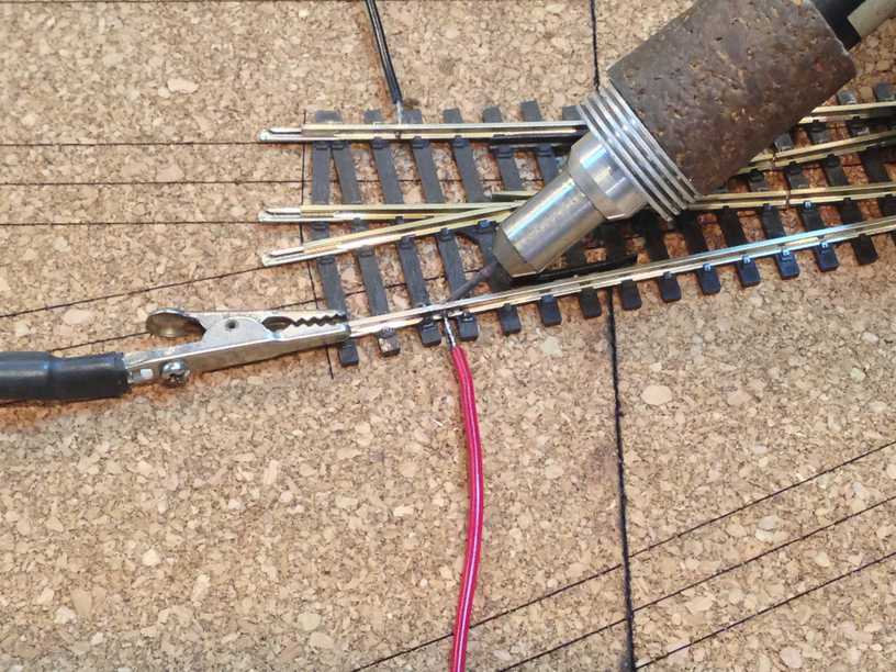
perfect time for the American Beauty to make an entry …….NO !!! its not Lady GaGa but rather a resistance soldering station ….In layman terms, the unit sends out a high current thru one of the electrodes , in this case the clip . The clip hooks on to the track and the circuit is completed by the probe. If there is any joint or break in between that creates a resistance to the current flow , then that joint heats up and any solder in it melts . When the current is removed the joint quickly cools down and the solder is completed. In our case the joint will be where the pre-soldered feeder wire meets the rail….
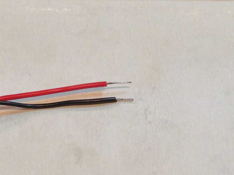
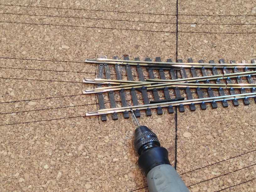
i tin the feeder wire and drill a 2 mm hole in the side of the rail……
and this how the setup looks now …..
A push of the foot switch and the solder joint is completed …… neat , clean and very strong …… with no ugly blobs of solder. Another big advantage of the resistance soldering method is that since the area which gets heated up is extremely small there is no danger of nearby ties being melted off . In later posts we will see how handy this feature is when assembling etched brass kits and other tasks around the layout …
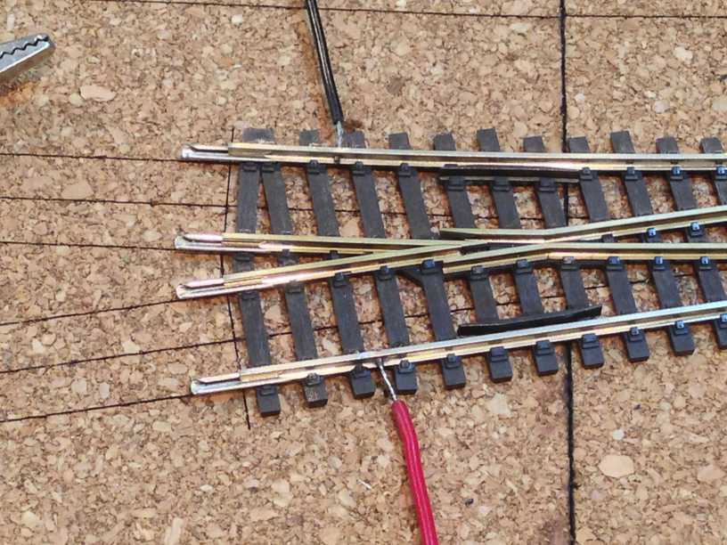
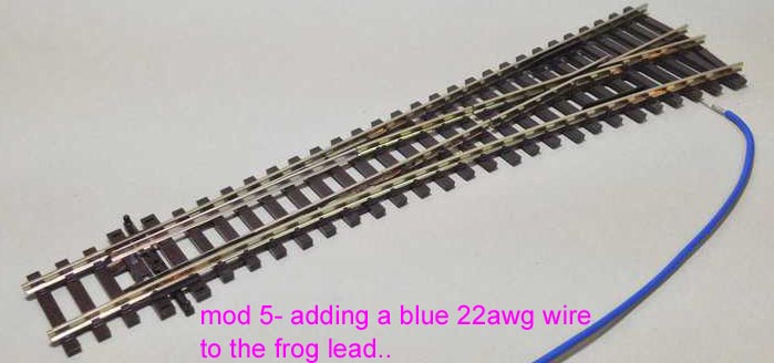
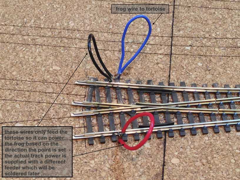
We had earlier soldered the blue frog wire to the point in mod 5 above…. . The red and black wire is now soldered in . However these are not the feeders which actually supply DCC power to the track. In fact these take power from the track and send them to the tortoise which in turn while switching the points, feeds the correct polarity current to the frog . Later when i dive underneath i will bunch them together , crimp on spade connectors and screw them on to the terminal block of the relevant Tortoise machine . Then i will come in and do the actual track feeders …… call me a glutton for punishment but it keeps the wiring sensible in the rats nest which will occur below decks as we forge further ahead ……
and the wires when pulled down underneath gives us a clean finish , the solder joints …which when painted and ballasted will all but disappear …..
another excursion below decks and i can easily ease in the extra long throwbar rod installed into the linkage bar of the point above and then screw in the other two screws completing the install …..
everything is nice and square and the tortoise throwbar holds the point rails against the stock rails with just the right pressure , not so hard so as to damage the linkage bar and neither so loose so as to cause derailments ……the extra long throwbar now needs to be dealt with …..
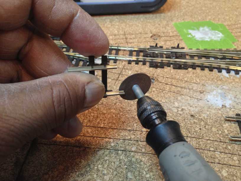
and i do so with a Dremel rotary drill loaded with a cut off disk ….. need to be careful while doing this . Continous friction would cause the the point linkage bar to melt so one needs to back off every few seconds , dissipate the heat build up with your fingers and then come back in till the throwbar cuts away ……
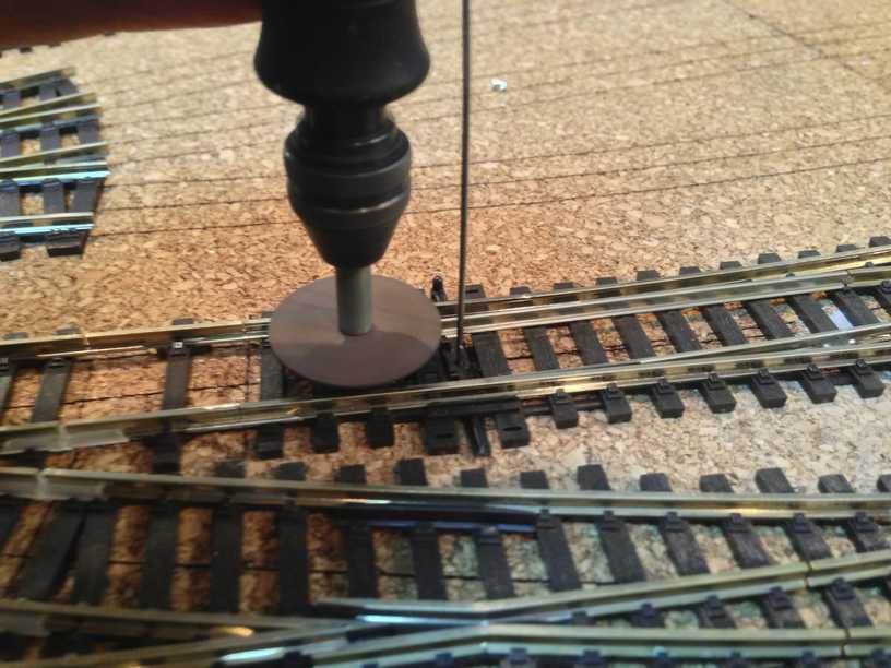
the angle of attack is crucial also to get a flush finish ……… patience and practice will get you there sure enough ……. and you would end up with something like this ..
that concludes our rather long essay on installing points and tortoises …..hope i did not bore you too much !!
previous in the series ….. installing electromagnets